Surveillance camera apparatus

Inactive Publication Date: 2004-02-19
PANASONIC I PRO SENSING SOLUTIONS CO LTD
View PDF7 Cites 26 Cited by
  • Summary
  • Abstract
  • Description
  • Claims
  • Application Information

AI Technical Summary

Problems solved by technology

The conventional surveillance camera apparatus thus constructed as previously mentioned, however, encounter such a problem that each of the pan motor and tilt motor is controlled by the controlling unit to have imaging unit move around each of the pan axis of the pan shaft and tilt axis of the tilt shaft without taking account of the slanted angle and the shape of the opening of the slanted plate portion of the housing assemb

Method used


Image

  • Surveillance camera apparatus
  • Surveillance camera apparatus
  • Surveillance camera apparatus

Examples


Example

[0063] Referring now to FIGS. 1 to 10 of the drawings, there is shown the preferred embodiment of the surveillance camera apparatus according to the present invention.

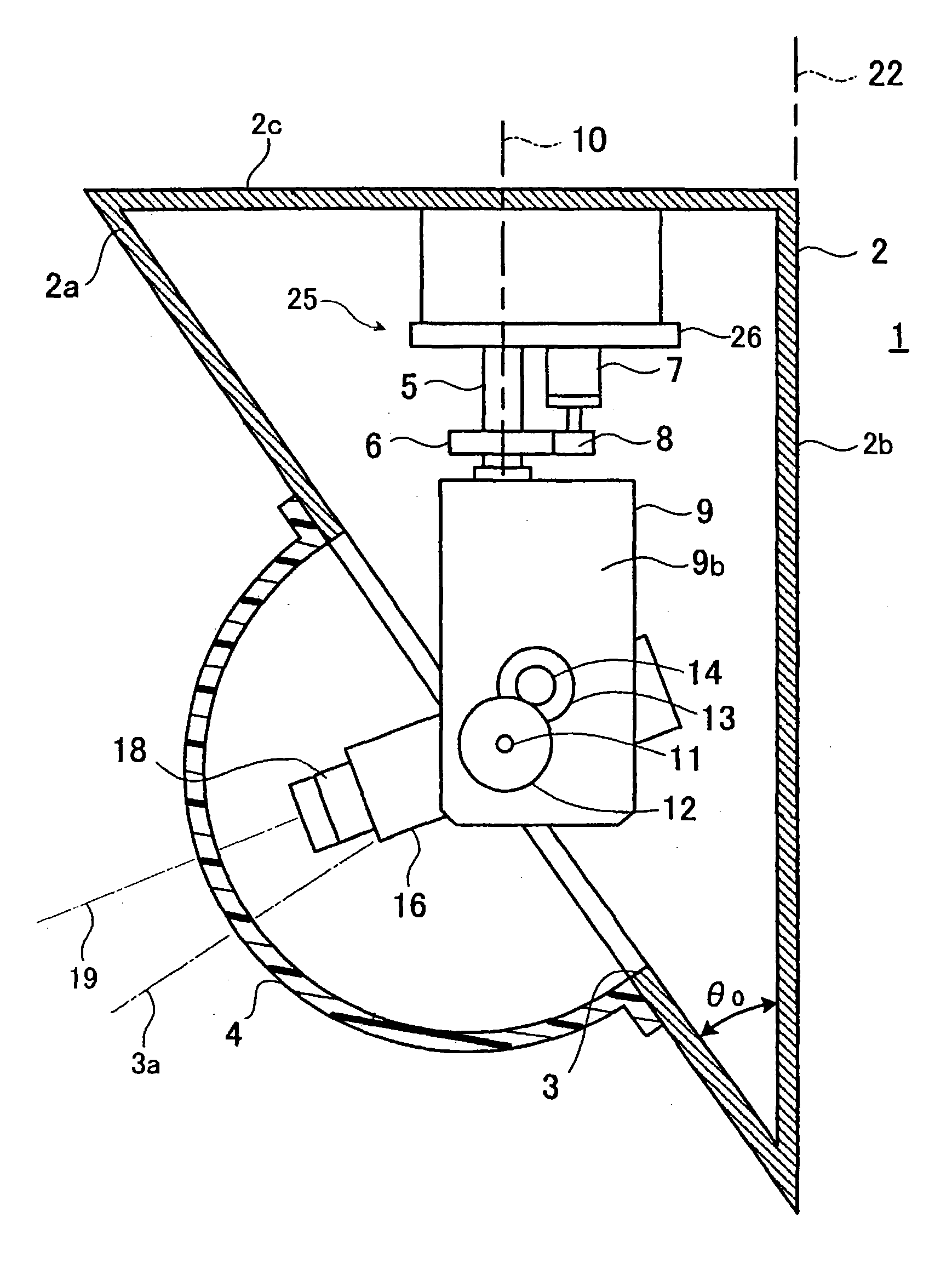
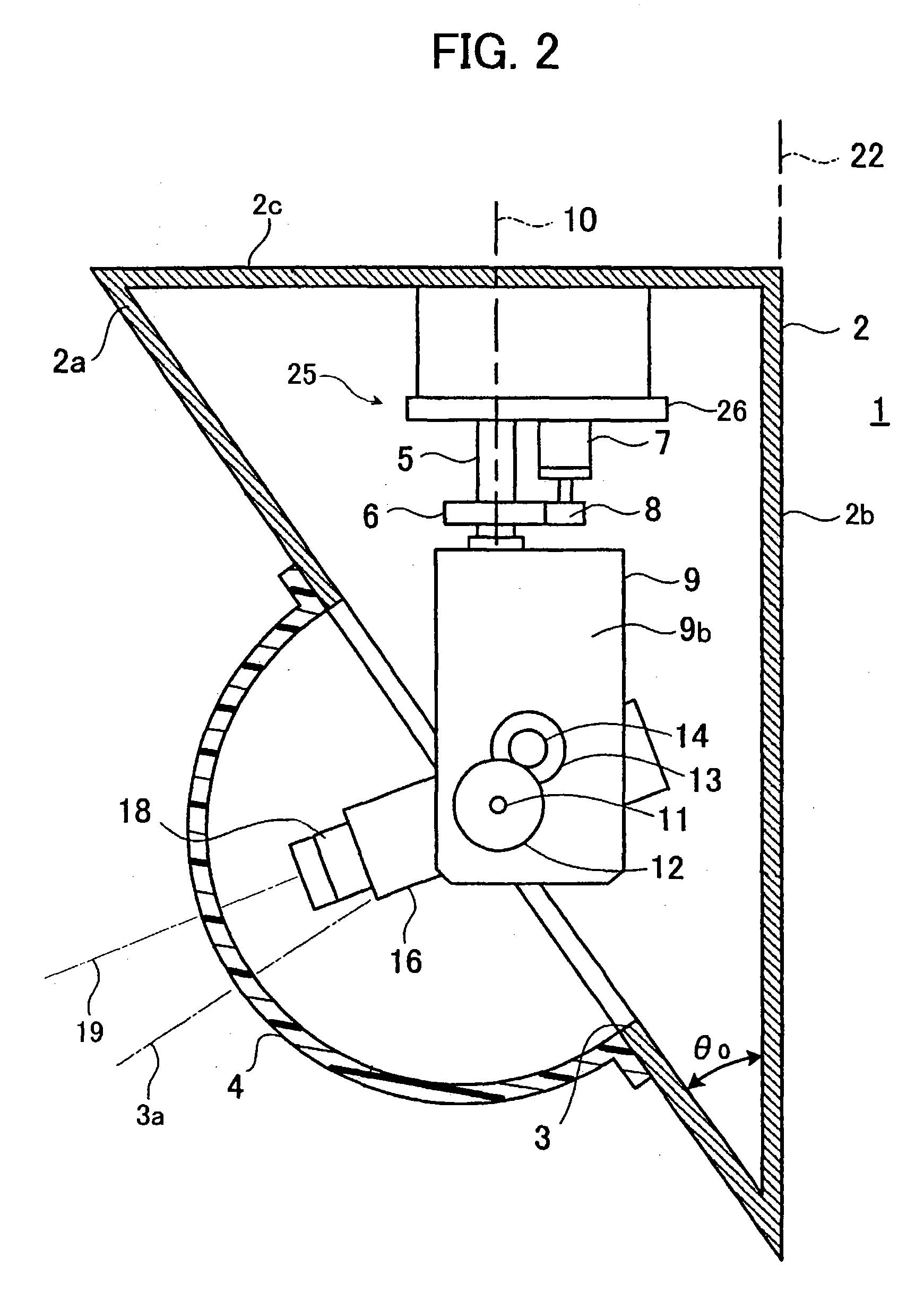
[0064] The preferred embodiment of the surveillance camera apparatus 1 is shown in FIG. 2 as comprising a housing assembly 2 having a slanted plate portion 2a with an inner surface, and a camera assembly 25 accommodated in the housing assembly 2. The slanted plate portion 2a forming part of the housing assembly 2 defines an opening 3 therein, while the opening 3 has a central axis thereof, the opening 3 having an imaginary inner surface flush with the inner surface of the slanted plate portion 2a forming part of the housing assembly 2, and the imaginary inner surface having the shape of a circle.

[0065] The camera assembly 25 includes a stationary member 26, a pan shaft 5 having a pan axis 10 thereof, a retaining member 9 integrally formed with the pan shaft 5, and a tilt shaft 11 having a tilt axis 15 thereof. The stat...


PUM


Abstract

Herein disclosed is a surveillance camera apparatus, comprising: a housing assembly having a slanted plate portion with an inner surface; and a camera assembly accommodated in said housing assembly, said slanted plate portion forming part of said housing assembly defining an opening therein, said opening having a central axis thereof, said opening having an imaginary inner surface flush with said inner surface of said slanted plate portion forming part of said housing assembly, and said imaginary inner surface of said opening having the shape of a circle, said camera assembly, including: a stationary member; a pan shaft having a pan axis thereof, said pan shaft being supported by said stationary member to be revolvable around said pan axis; a retaining member integrally formed with said pan shaft; a tilt shaft having a tilt axis thereof, said tilt shaft being retained by said retaining member to be revolvable around said tilt axis under the state that said tilt axis of said tilt shaft is in perpendicular relationship with said pan axis of said pan shaft; an imaging unit for taking an image of a specific object through said opening of said slanted plate portion forming part of said housing assembly, said imaging unit having a light axis thereof, said imaging unit being integrally supported by said tilt shaft under the state that said light axis of said imaging unit is in perpendicular relationship with said tilt axis of said tilt shaft; a pan motor for having said pan shaft driven around said pan axis; and a controlling unit for controlling said pan motor to have said pan motor move said imaging unit around said pan axis of said pan shaft in response to the revolution of said tilt shaft to be driven around said tilt axis.

Description

[0001] 1. Field of the Invention[0002] The present invention relates to a surveillance camera apparatus, and more particularly to a surveillance camera apparatus partially constituting a surveillance system for watching a specific object such as for example unqualified people and other intruders intruding into a special room that does not permit people without permission to enter.[0003] 2. Description of the Related Art[0004] Up until now, there have been proposed a wide variety of conventional surveillance camera apparatus comprising a housing assembly having an opening, and a camera assembly accommodated in the housing assembly, the camera assembly taking an image of a specific object through the opening of the housing assembly.[0005] One typical example of the conventional surveillance camera apparatus of this type comprises a housing assembly 100 and a camera assembly 125 accommodated in the housing assembly 100. The housing assembly 100 is shown in FIG. 13 as including a slante...

Claims


Application Information

Patent Timeline
IPC IPC(8): G03B17/00G03B17/18G03B15/00G03B17/56G08B13/196H04N5/222H04N5/225H04N7/18
CPCG08B13/19619H04N7/18G08B13/19689G08B13/1963
Inventor WADA, JOUJIKAJINO, TETSUROUFUJIWARA, YOSHIHIROGUERRERO, GIL PALMA JR.
Owner PANASONIC I PRO SENSING SOLUTIONS CO LTD
Why Eureka
Try Eureka