Sensor with selectable sensing orientation used for controlling an electrical device

a technology of sensing orientation and electrical devices, applied in the direction of free standing, coupling device connection, lighting and heating apparatus, etc., can solve the problems of not being able to easily move, the installation is not easy to move, and the arrangement is relatively expensive and requires installation

Inactive Publication Date: 2010-12-02
BEON LIGHT CORP PTY LTD
View PDF7 Cites 79 Cited by
  • Summary
  • Abstract
  • Description
  • Claims
  • Application Information

AI Technical Summary

Benefits of technology

[0009]In accordance with one aspect of the invention, there is provided a portable device for controlling an electric device, including a sensor respon

Problems solved by technology

This arrangement is relatively expensive and requires installation by an electrician.
Additionally, the installation is not easily moved once it is fixed in place and wired into the mains power supply.
This arrangement may not, however, allow for the field of view of the motion sensor to be directionally targeted.
Thus, in situations where it is not desired to switch the light based on motion in a certain part of the room, the light will nonetheless be undesirably switched on.
Thus, the 360° range of the assembly described by Young lacks direction

Method used


Image

  • Sensor with selectable sensing orientation used for controlling an electrical device
  • Sensor with selectable sensing orientation used for controlling an electrical device
  • Sensor with selectable sensing orientation used for controlling an electrical device

Examples


Embodiment Construction

[0040]In this specification, and specifically including the description and drawings, like reference numerals indicate like features, functions or parts, unless otherwise indicated.

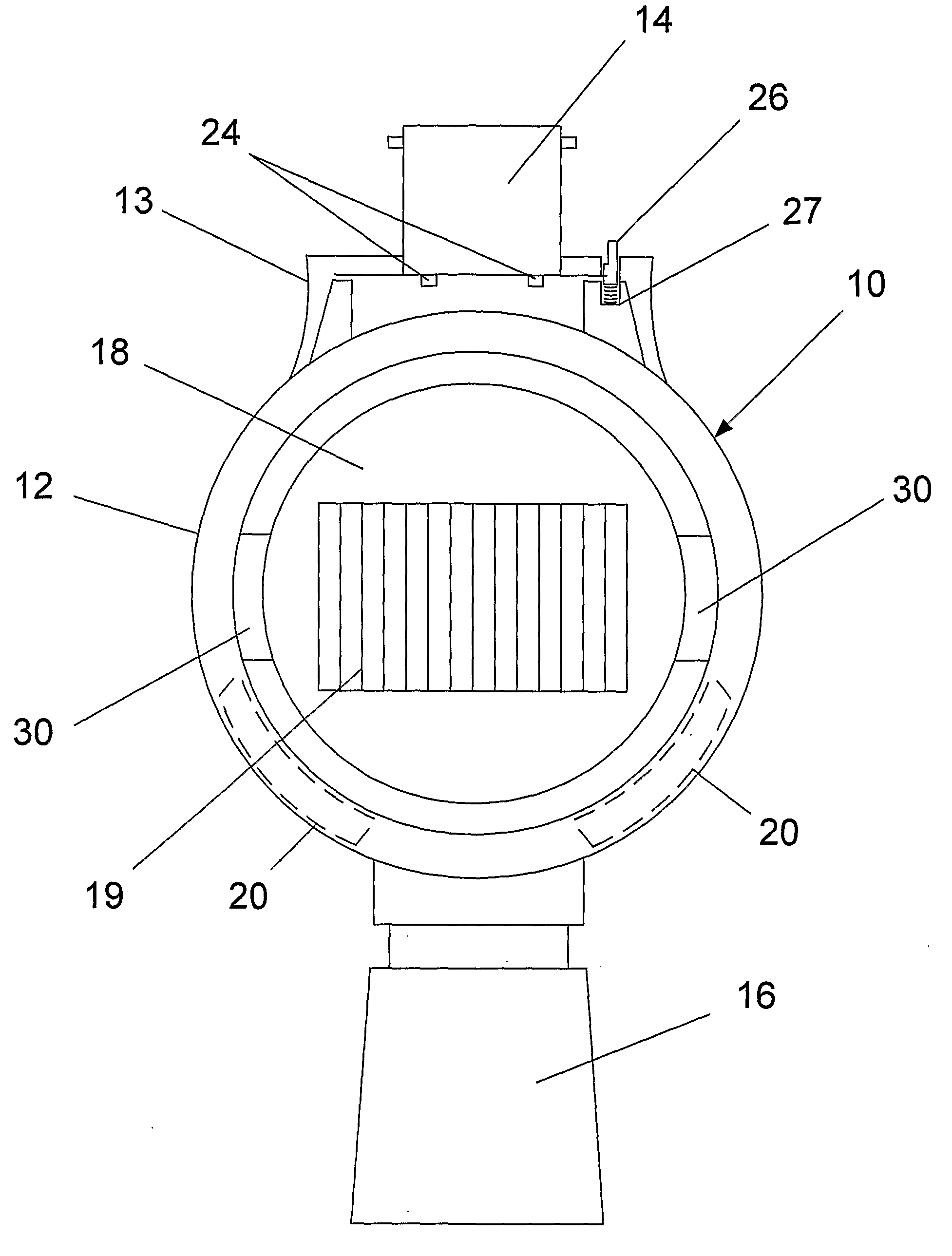
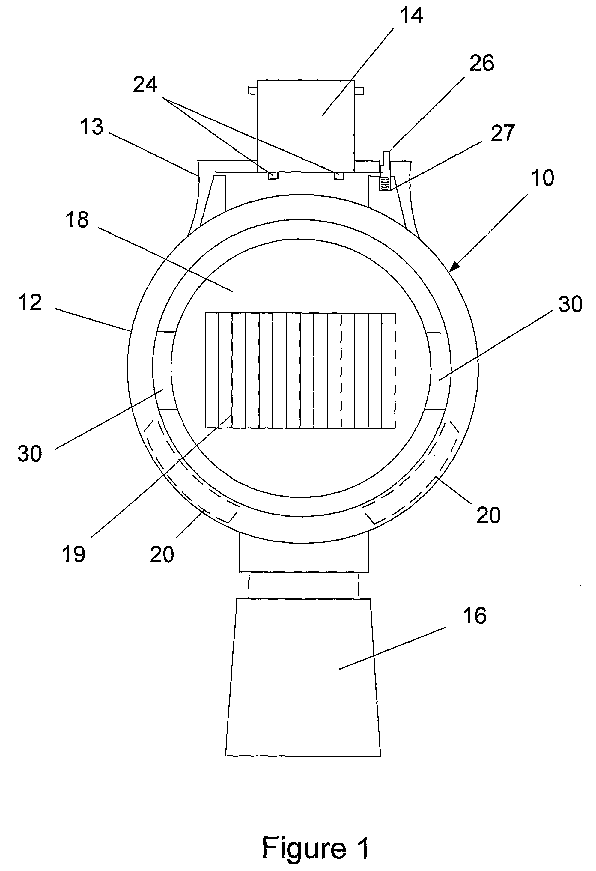
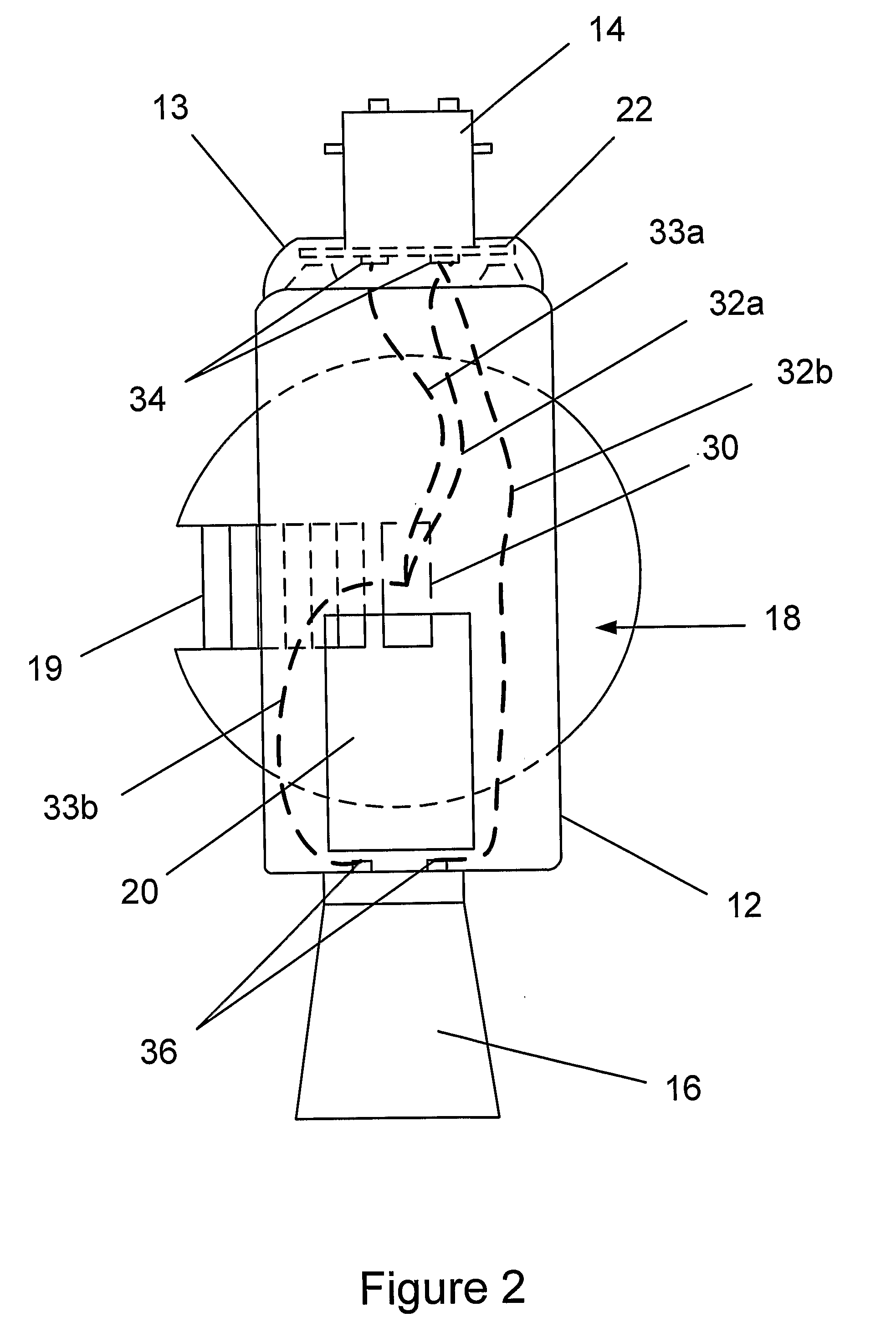
[0041]Referring to FIGS. 1 to 3, there is shown an adaptor 10 having a housing 12 of a generally shallow cylindrical shape. A motion detector 18 (also termed a motion sensor) is located within the cylindrical body of the housing 12 and connected thereto by housing connectors 30. The housing connectors 30 allow rotation of the motion detector 18 relative to the housing 12 about a lateral (or generally horizontal) axis extending through the housing connectors 30 and the center of the motion detector 18.

[0042]At a top end of the housing 12 is mounted a top housing part 13 having a plug part 14 connected thereto. The plug part 14 is configured to be inserted into a light socket such as is commonly used for domestic lighting in Australia. The arrangement or configuration by which the plug part 14 engages with ...


PUM


Abstract

A device designed to be plugged directly into a household power supply socket comprising a sensor for controlling an electrical device, the sensor having selectable sensing orientation and being one of a motion detector, an infrared detector, a photodetector or a sound detector, whereby the sensor generates a control signal to the electrical device, the electrical device being one of a light bulb, a mobile telephone, a security device such as a sound or burglar alarm, or a monitoring device such as a surveillance camera, upon detection of a change in an environment, e.g. movement, ambient light, sound, etc.

Description

FIELD OF THE INVENTION[0001]The present invention relates to a portable device. In particular, the present invention relates to a portable device for controlling an electric device.[0002]In the context of this specification, “gimbal” means a device with two mutually perpendicular axes of rotation, thus giving free angular movement in two directions, on which an object may be mounted.BACKGROUND OF THE INVENTION[0003]In recent years, various automatic switching devices have been marketed, which function to switch lighting on and off, depending on some sensed condition. For example, an ambient light level sensor may be incorporated into the switching device so as to switch on the light when the ambient light falls below a certain level (e.g. when night falls). Alternatively, there may be a motion sensor for detecting motion within a particular field of view of the detector and switching the light on when motion is detected.[0004]One known motion detector arrangement for switching light...

Claims


Application Information

Patent Timeline
IPC IPC(8): H01H35/00
CPCF21S6/002F21S6/005F21V17/02Y02B20/44F21V23/0442H01R33/945H05B37/0209F21V19/006H05B47/115Y02B20/40F21S6/00H01R13/6683H01R33/00H05B47/105
Inventor MURRAY, PETER GRAHAMEJACKEL, JEFFREY LAURANCE
Owner BEON LIGHT CORP PTY LTD
Why Eureka
Try Eureka