
Filter assembly and image enhancement system for a surveillance camera and method of using the same

a technology of surveillance camera and filter, which is applied in the field of filter assembly and image enhancement system, can solve problems such as degrading image quality, and achieve the effect of reducing glar

Inactive Publication Date: 2008-10-16
KESTERSON JOHN
View PDF13 Cites 76 Cited by
  • Summary
  • Abstract
  • Description
  • Claims
  • Application Information

AI Technical Summary

Benefits of technology

[0009]The invention comprises a filter assembly and image enhancement system adapted to be used with an optical device such as a camera. The filter assembly is adapted to prevent some wavelengths and / or orientations of light from reaching the camera's aperture. In one embodiment, the filter assembly is adapted to reduce glare caused by a bright light reflecting off of a vehicle's windshield, a pane of glass, a chrome reflector, or the like. The filter assembly can also be used to create an image in which the visible light spectrum is blocked and only infrared light is allowed to reach the camera sensor. The filter assembly can also be used as an adjustable neutral density filter to attenuate the amount of light that reaches the camera aperture.
[0010]In one embodiment, the filter assembly comprises three filters adapted to be independently movable between a first position, wherein they are not in front of the camera's aperture, and a second position, wherein they are in front of the camera's aperture. In the second position one or more of the filters prevent certain wavelengths or orientations of light from reaching the camera's aperture.
[0011]In one embodiment, the first and second filters are polarizing filters adapted to remove certain orientations of visible light. In addition to moving between its first position and its second position, the second filter is also adapted to rotate up to 360 degrees. The rotation of the second filter helps to optimize the reduction of glare because the angle of the polarized light reflecting from objects in the environment can change if the angle of the light source, i.e. sun, changes. The third filter is an IR filter adapted to block certain wavelengths of infrared light.
[0012]The independent movement of the three filters allows multiple filter configurations for different light conditions and user preferences. In one filter configuration, a single polarizing filter (the first filter or the second filter) can be moved to its second position in front of the aperture to remove polarized light and reduce glare reflected from objects in the environment. In another filter configuration, both polarizing filters can be moved to their second position to create an adjustable neutral density filter. This cross polarizing neutral density filter can be used to attenuate very bright light from a scene. To create the neutral density effect, both of the polarizing filters are moved to their second position in front of the camera aperture. The second filter is then rotated. The light passing to the aperture will go from being fully bright to full dark as the second filter rotates through a 90 degree arc relative to the stationary first polarizing filter. This is especially important when using high resolution and very sensitive cameras. Sometimes bright sunlight, especially if it is reflecting from chrome or glass, can be too bright for the camera. Many cameras are equipped with an iris to stop down the light, but when the iris is closed too much it can degrade the quality of the image. By leaving the iris open and inserting the adjustable neutral density filter (by using the two cross polarizing filters) a much better image is produced.
[0013]In most configurations, the IR filter remains in its second position thereby removing IR light and allowing only visible light to fall on the camera's sensor. However, in at least one filter configuration, the IR filter is removed and the two polarizing filters are adjusted to be fully cross-polarized thereby blocking all visible light, but allowing some IR light to pass. This configuration is especially useful when photographing scenes that are illuminated by an IR light source. By blocking visible light and allowing only IR light through to the camera's aperture, the user can sharply focus the scene. This is because most lenses are corrected for visible light, but not corrected for IR light.

Problems solved by technology

Many cameras are equipped with an iris to stop down the light, but when the iris is closed too much it can degrade the quality of the image.

Method used


Image

  • Filter assembly and image enhancement system for a surveillance camera and method of using the same
  • Filter assembly and image enhancement system for a surveillance camera and method of using the same
  • Filter assembly and image enhancement system for a surveillance camera and method of using the same

Examples


Embodiment Construction

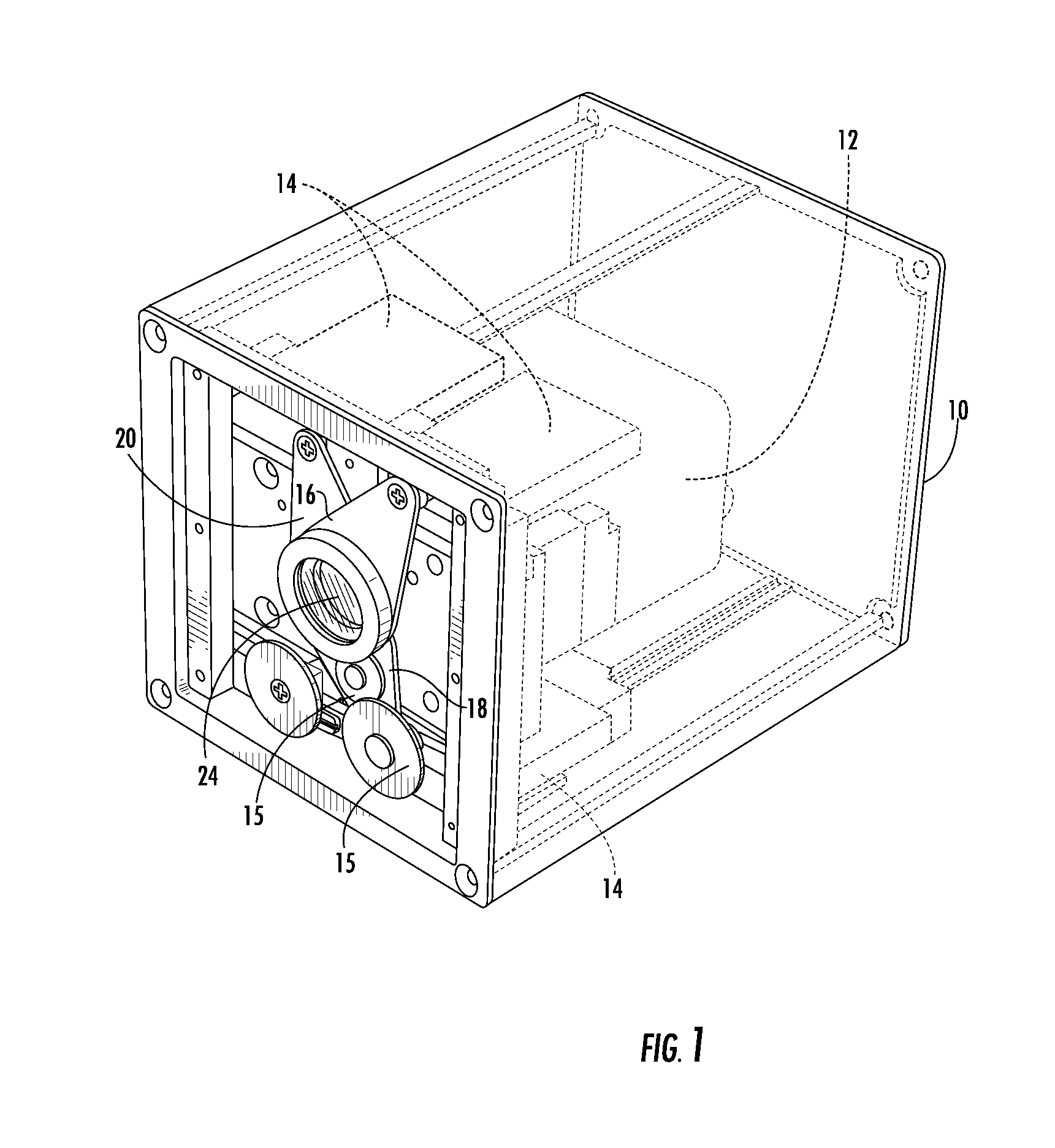
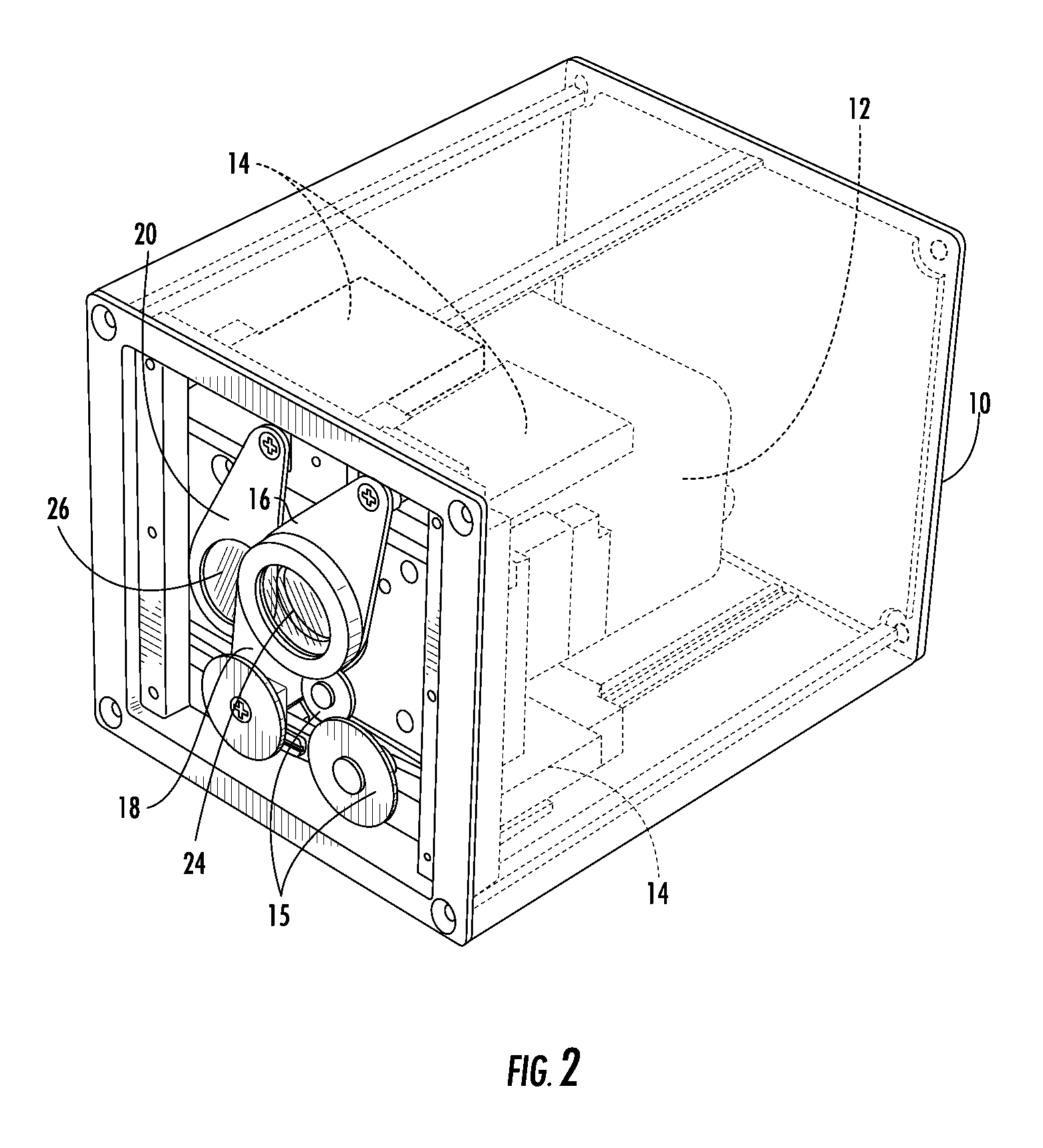
[0025]The invention comprises a filter assembly and image enhancement system adapted to be used with an optical device such as a camera 12, binoculars, telescope, telephoto lens, or gun scope. Although the invention may be used with any suitable optical device, for simplicity the invention will be described herein as being used with a camera 12. The filter assembly is adapted to prevent certain orientations and / or wavelengths of light from reaching the aperture of the camera 12. In one embodiment, the filter assembly comprises three filters 22, 24, 26 adapted to be independently moved between a first position, wherein they are not in front of the camera's 12 aperture, and a second position, wherein they are in front of the camera's 12 aperture.

[0026]FIGS. 1-3 show an embodiment wherein a camera 12 is mounted in a housing 10. The filters 22, 24, 26 are combined with swing arms 16, 18, 20 which are operatively combined with motors 14. The motors 14 are adapted to move the swing arms 1...


PUM


Abstract

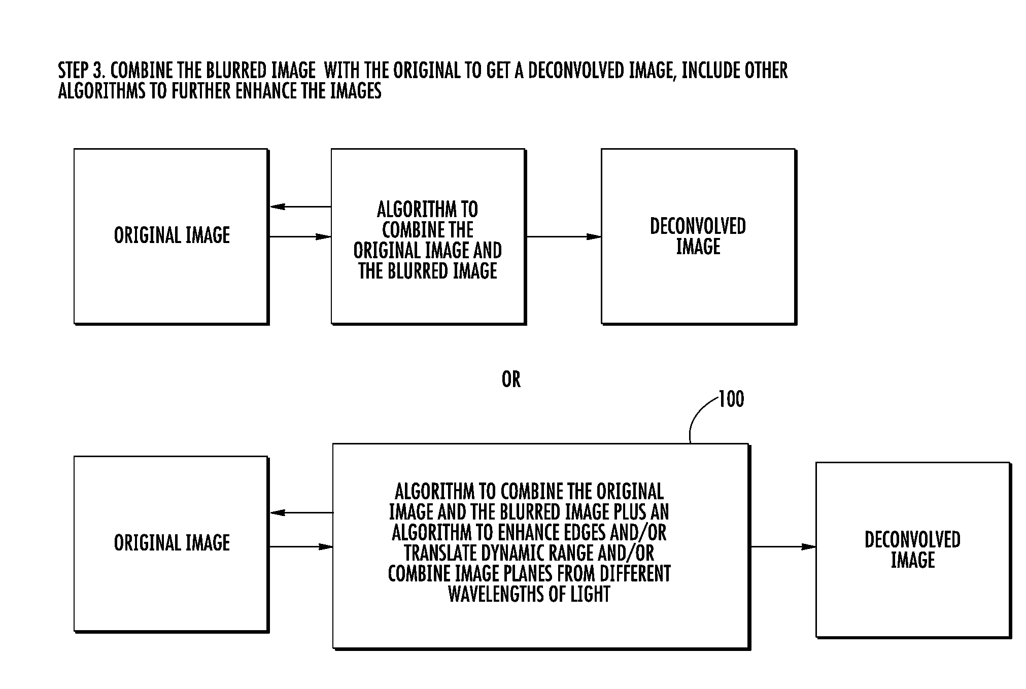
A filter assembly adapted to be used with a camera for selectively controlling the light that reaches the camera's aperture. In one embodiment, the filter assembly comprises three filters adapted to be independently moved between a first position wherein they are not in front of the camera's aperture and a second position wherein they are in front of the camera's aperture. The first and second filters are polarizing filters adapted to block portions of visible light. The third filter is an infrared filter adapted to block infrared light. In addition to moving between its first position and its second position, the second filter is also adapted to rotate up to 360 degrees. The image captured by the camera may be improved using a computer implemented image enhancement system that uses one or more of multi-spectral imaging, deconvolution, edge enhancement, and dynamic range translation.

Description

BACKGROUND OF THE INVENTION[0001]This application is based upon U.S. Provisional Application Ser. No. 60 / 911,640 filed Apr. 13, 2007, the complete disclosure of which is hereby expressly incorporated by this reference.[0002]The present invention relates to a filter assembly and an image enhancement system for use with an optical device such as a camera. More particularly, the invention relates to a filter assembly that selectively prevents some wavelengths and / or orientations of light from passing to a camera's aperture and then uses a computer to enhance the image.[0003]Surveillance cameras are used for a variety of purposes, including taking pictures (including video) of a subject without the subject's knowledge. To prevent the subject from knowing that his / her picture is being taken, it is often necessary for the pictures to be taken while the photographer and subject are in different rooms or in different vehicles or separated by a distance. However, sunlight and / or bright indoo...

Claims


Application Information

Patent Timeline
Patent Type & Authority Applications(United States)
IPC IPC(8): G01J3/00G02B27/28
CPCG01J2003/1213G01J2003/1243G02B5/208G02B27/28H04N5/2254H04N5/238H04N5/33H04N23/55H04N23/75
Inventor KESTERSON, JOHN
Owner KESTERSON JOHN
Learn More