Surface heating system and method for producing it and a heatable object

a surface heating and heatable object technology, applied in the field of seats, can solve the problems of insufficient heat distribution over the area, damage to the cushion layer and/or the heating wire, and the need for a costly and appropriately designed seat construction,

Inactive Publication Date: 2004-02-26
BRAINSTOCK COM
View PDF6 Cites 27 Cited by
  • Summary
  • Abstract
  • Description
  • Claims
  • Application Information

AI Technical Summary

Benefits of technology

[0022] Furthermore, it is advantageous to design a manually and / or electrically / electronically operable and / or automatic current control that can be connected to a power source and hooked up to the current conducting wires whose contact terminals are in contact with the heating layer.

Problems solved by technology

This necessitates not only a costly construction of an appropriately designed seat, but it also has disadvantages in particular in operation.
For instance, because of the stronger heating of surrounding layers in the immediate vicinity of the heating wires there is a danger of overheating, which can lead to damage to the cushion layers and / or the heating wires and even cause a fire.
Furthermore, the heat distribution over the area is not optimum, since the temperature is always higher in the region of the heating wires than at a distance from them.
Also disadvantageous with this known style is the mechanical stress to which the heating wires are subjected when a passenger uses the seat, since the conducting wires can break because of this, which can lead to failure of operation and / or can have as a consequence another source of fire.
Thus, heating elements with electrically conductive plastic are indeed known, but in all of the prior art there is no data or hints of how such heating elements are to be designed and produced in order to be able to use them in practice.
The use of a film of electrically conductive plastics on the support structure of a vehicle seat, however, is not possible, since all the cushion layers lying on top, etc., would have to be heated for the heat to reach a sitting passenger, which would involve a great deal of energy.
In particular for sitting or reclining supports there are no known usable surface heating systems with electrically conductive plastics.

Method used


Image

  • Surface heating system and method for producing it and a heatable object
  • Surface heating system and method for producing it and a heatable object
  • Surface heating system and method for producing it and a heatable object

Examples


Embodiment Construction

[0042] The same reference numbers are used throughout for the same or equivalent parts in the following description of the invention using the embodiment examples. Even though not all details of the graphic representations are treated in the following description the individual characteristics and their relationships to the extent that they are represented in the figures easily follow for a specialist from the drawings.

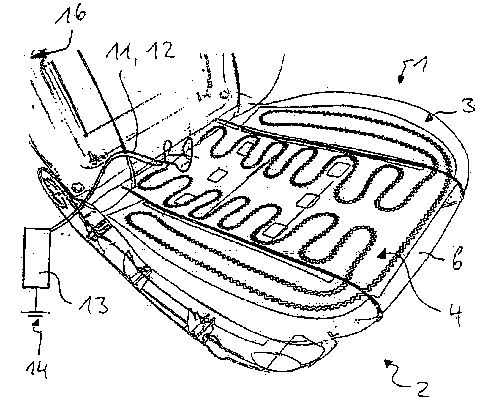
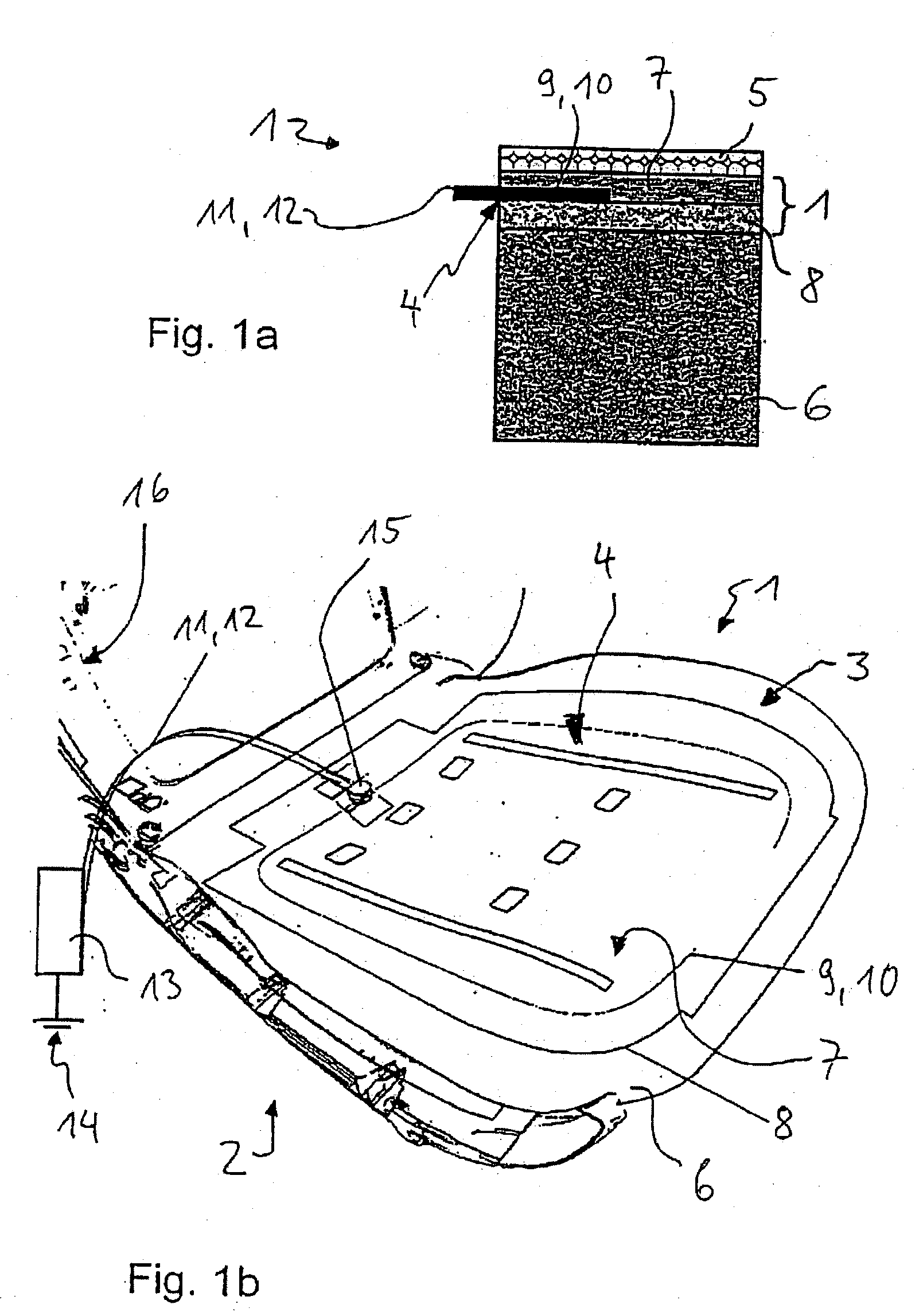
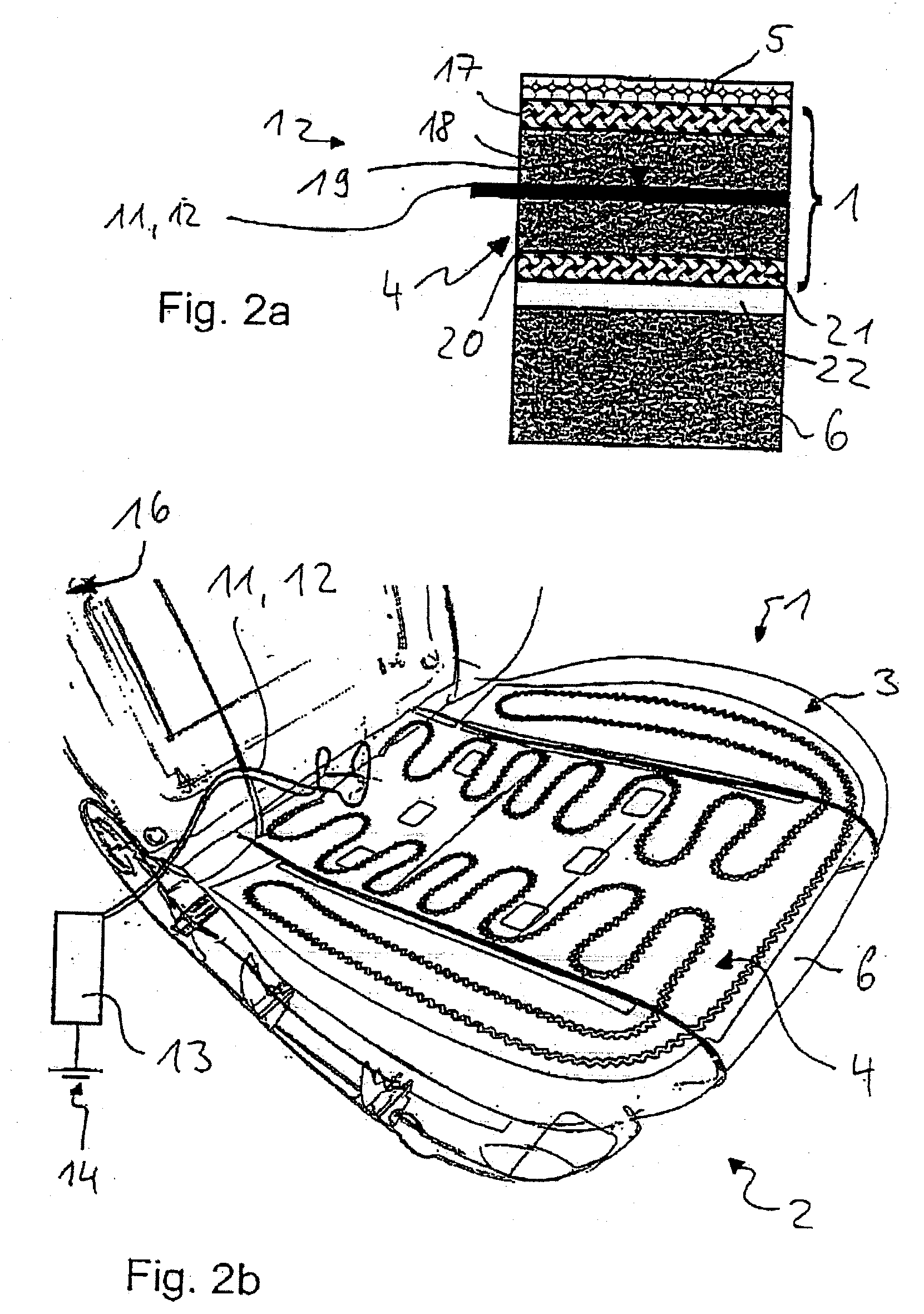
[0043] As a first embodiment example of a surface heating system 1 a vehicle seat 2 in which a seat heating system 4 is integrated into its seat bottom 3 is shown in FIGS. 1a and 1b in a sectional and perspective view.

[0044] The construction of the seat bottom 3 in the vicinity of the surface heating system 1 is shown in FIG. 1a, in which a cross section through the corresponding layers / components of the seat bottom 3 is shown. The surface of the seat bottom 3 is formed by a seat cover 5, which can consist of fabric, synthetic leather or leather or other suitable mate...


PUM

PropertyMeasurementUnit
sizeaaaaaaaaaa
thicknessaaaaaaaaaa
thicknessaaaaaaaaaa

Abstract

A surface heating system consists of a support and a heating layer that contains an electrically conductive plastic. The heating layer is formed by a flexible film. A heatable object made as such a surface heating system. A method for producing a surface heating system, where a heating layer containing an electrically conductive plastic bonded to a support, and where the heating layer is formed by initially applying an electrically conductive, especially a foam plastic material onto the support and then hardening the plastic material on the support. Alternatively, the method produces a surface heating system with a heating layer of an electrically conductive plastic is bonded to a support. The heating layer is produced from an electrically conductive, especially a foam plastic material, and then arranged on the support. Another alternative of the method consists of bonding a heating layer with an electrically conductive plastic to a support. A fabric is produced as the support. Contact terminals from power supply wires are woven into the fabric when it is made or afterwards, and then a heating layer is applied to the support and the contact terminals.

Description

[0001] This application is a continuation of PCT International Application No. PCT / DE01 / 04879, filed Dec. 21, 2001, the contents of which are here incorporated by reference in their entirety.[0002] 1. Field of the Invention[0003] The invention relates to a novel surface heating system, a heatable object with the novel surface heating system and a method for producing the novel surface heating system. More particularly, this invention relates to a seat heating system, a heated seat and a method for producing it. Preferably, the invention additionally relates to a heating system for side panels and floor coverings, in particular in motor vehicles, side panels and floor coverings outfitted with such heating system in particular in motor vehicles and a method for producing them. Furthermore, this invention relates in particular to a mattress heating system, a heated mattress and a method for producing it.[0004] 2. Prior Art[0005] Seat heating systems are known from practice, for example...

Claims


Application Information

Patent Timeline
Patent Type & Authority Applications(United States)
IPC IPC(8): H05B3/14H05B3/34
CPCH05B3/146H05B3/34H05B2203/034H05B2203/017H05B2203/029H05B2203/013
Inventor DIEMER, STEPHANDIEMER, MICHAEL
Owner BRAINSTOCK COM
Why Eureka
Try Eureka