While such density variations are gradually eliminated as the image forming operation is repeated a few times, if the operation-suspended state lasts for long, a longer period of time will be necessary to eliminate density variations and an
image quality may deteriorate even to a measurable extent in some cases.
This causes a problem that it is difficult to accurately adjust the density
control factor based on a density of the patch image and it therefore is difficult to form a stable image.
That is, a major cause of such a variation density is that as toner is left adhered to a surface of a toner carrier for a long period of time, a bond between the toner carrier and the toner becomes gradually strong and therefore larger force becomes necessary to separate the toner from the toner carrier, and that since a surface condition of the toner carrier in suspension is not uniform but is rather uneven due to different densities of the toner which is in contact with the surface of the toner carrier at different positions or for other reason, the strength of the bond between the toner carrier and the toner is also uneven.
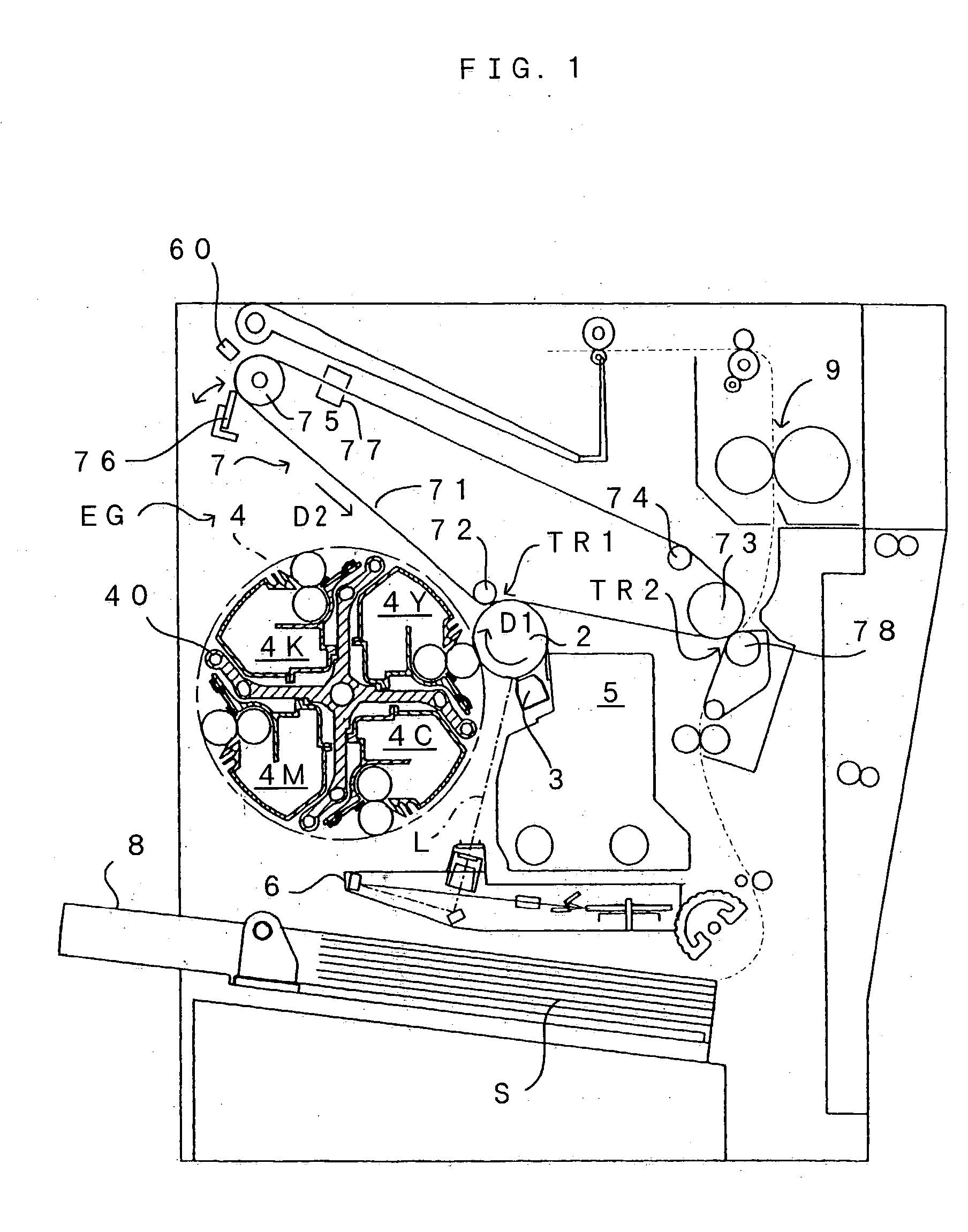
The condition of the surface of the intermediate transfer belt 71 is not always optically uniform, and fused toner during use may gradually lead to discoloration,
dirt, etc.
When a foundation profile, a density of a patch image or the like is calculated based on such sample data which contain superimposed noises and density control factors are set in accordance with the result of the calculation, it may become impossible to set each density
control factor always to a proper condition and an
image quality may deteriorate.
However, since it becomes impossible to obtain a sufficient
noise removing effect and an error may intensify depending on a choice of these numbers, it is desirable to carefully determine these numerical figures in view of the following points.
That is, extraction of too short a section of a data string as compared to the frequency of noises pushes up the possibility that noises are not included in the section within which spike-like
noise removal will be executed and increases the number of calculations, and therefore, is not efficient.
On the other hand, extraction of too long a section ends up in averaging out even significant variations in sensor output, namely, variations which represent a
density change of an object of detection, and thus makes it impossible to correctly calculate a density profile despite the original purpose.
Further, since the frequency of noises is not constant, uniform removal of a predetermined number of largest or smallest data pieces from an extracted data string may result in removal of data such as data pieces Vp(11) and Vp(14) which do not contain noises, or on the contrary, may fail to sufficiently remove noises.
On the other hand, when the
noise-containing data pieces are left not removed, replacement of the other data pieces with an average value calculated including these noise-containing data pieces may increase an error.
However, since conventional filtering changes not only noise-containing data but also neighboring data from original values although it is possible to make a noise waveform less sharp, a large error may arise depending on the state of noises.
This is a major cause of shutdown-induced banding.
Solid adhesion of the
fine powder components therefore easily occurs on the surface of the developer roller 44, which in turn easily leads to shutdown-induced banding.
Hence, an apparatus which comprises such a developer roller easily gives rise to shutdown-induced banding.
However, at the time of acquisition of the foundation profile of the intermediate transfer belt 71, a such toner movement is not desirable.
Since the
mass, the
electrification amount and the like of toner having various particle diameters are different, when an image is formed with the toner having such a particle
diameter distribution, use of these toner is not uniform.
Hence, in a conventional image forming apparatus in which each density control factor is controlled so that output voltages from a density sensor will be constant, a variation in
image density because of a variation in toner characteristic is unavoidable and it therefore is not always possible to obtain a satisfactory
image quality.
While to calculate from an integrated value of the number of formed images is the simplest method of estimating the remaining amount of the toner, it is difficult to learn about an accurate remaining amount with this method since the amount of the toner consumed by formation of one image is not constant.
Although all patch images may be formed to have the length L1 on the contrary, in this case, there arises a problem that a
processing time and the consumption of toner increase.
Therefore, the output
voltage data from the sensor as they directly are hard to be handled as information which is for evaluating the amount of the adhering toner.
Of course, although the optimal value Vop may be calculated by other method, e.g., using a more accurate approximate function, this is not always practical considering a detection error of the apparatus, a variation among apparatuses, etc.
To increase the average developing bias Vavg to further increase an
image density in an area wherein the growth rate of the
image density is small ends up in excessively increasing the toner consumption although a very large increase in density can not be expected, and as such, is not practical.
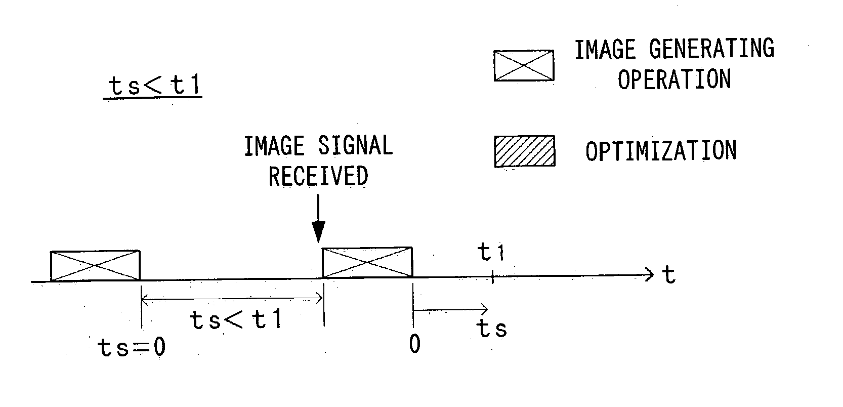
It is thus difficult to uniformly determine the first predetermined period t1.
However, too frequent execution of optimization of density control factors based on patch image densities increases the consumption of toner which is used during formation of patch images.
This increases the frequency of supplying of toner (or exchange of the developer) particularly in a small-size image forming apparatus in which only small amounts of toner can be housed in the developers, which in turn lowers the convenience of the apparatus and pushes up a running cost of the apparatus.


