Frame interpolation and apparatus using frame interpolation

a frame interpolation and apparatus technology, applied in the field of frame interpolation and apparatus using the method of frame interpolation, can solve problems such as gap or superimposition in the frame to be interpolated, interpolation technique solving this problem, and compensating frame interpolation techniqu

Active Publication Date: 2004-03-11
FLEXIWORLD TECH
View PDF4 Cites 82 Cited by
  • Summary
  • Abstract
  • Description
  • Claims
  • Application Information

AI Technical Summary

Problems solved by technology

Nevertheless, this frame interpolation technique could assign an error motion vector in a still background, different from a motion vector to be assigned, due to relatively not so high correlation between objects in a first frame and a second frame.
This erroneous motion-vector assignment results in displaying the background on an image area on which the object should be displayed.
As discussed, one known m...

Method used


Image

  • Frame interpolation and apparatus using frame interpolation
  • Frame interpolation and apparatus using frame interpolation
  • Frame interpolation and apparatus using frame interpolation

Examples


first embodiment

[0063] (First Embodiment)

[0064] A method of frame interpolation, a first embodiment of the present invention, will be disclosed with reference to FIGS. 1 to 11.

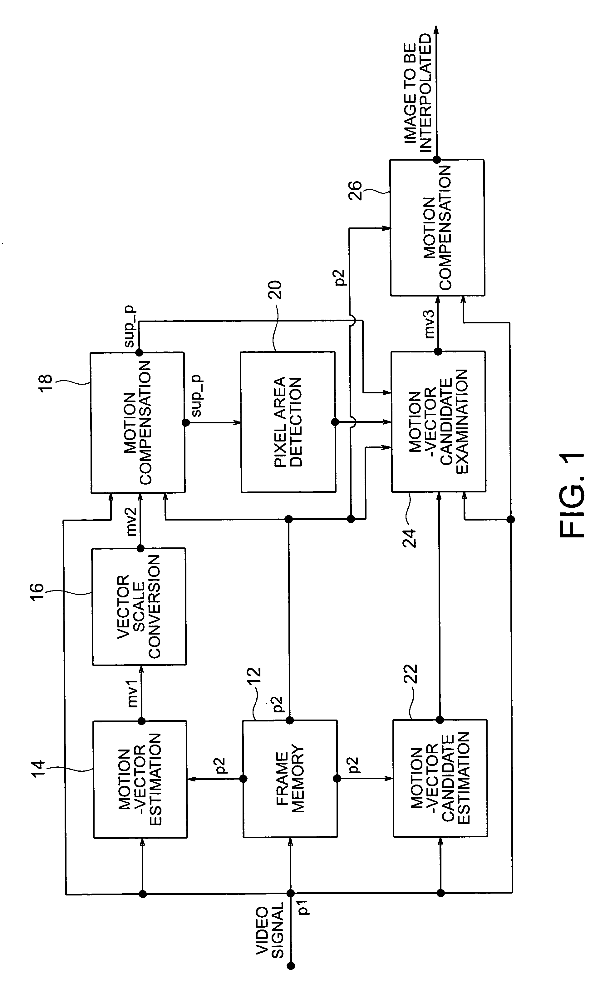
[0065] Shown in FIG. 1 is a frame interpolation apparatus that executes the first embodiment of frame interpolation.

[0066] The frame interpolation apparatus shown in FIG. 1 is equipped with a frame memory 12, a motion-vector estimator 14, a motion-scale converter 16, a motion compensator 18, a pixel area detector 20, a motion-vector candidate estimator 22, a motion-vector candidate examiner 24, and another motion compensator 26.

[0067] The first embodiment of frame interpolation will be disclosed in up-converting a 60-Hz non-interlaced video signal into a 120-Hz non-interlaced video signal, although this invention is not limited to this application.

[0068] Reference signs p1 and p2 shown in FIG. 1 indicate a first reference frame and a second reference frame, respectively, of an input video signal. The first reference frame p1 ...

second embodiment

[0120] (Second Embodiment)

[0121] A method of frame interpolation, a second embodiment of the present invention, will be disclosed with reference to FIGS. 12 to 28.

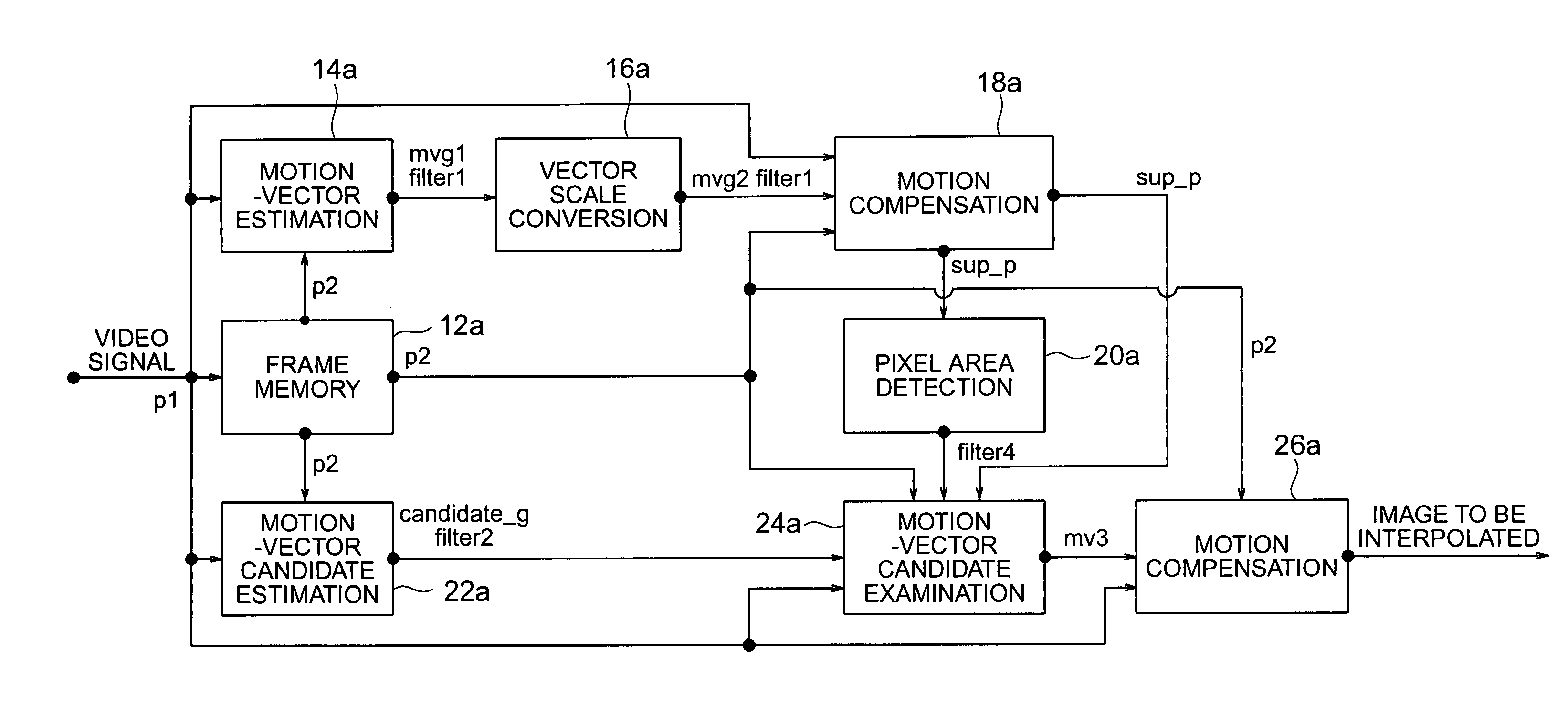
[0122] Shown in FIG. 12 is a frame interpolation apparatus that executes the second embodiment of frame interpolation.

[0123] The frame interpolation apparatus shown in FIG. 12 is equipped with a frame memory 12a, a motion-vector estimator 14a, a motion-scale converter 16a, a motion compensator 18a, a pixel area detector 20a, a motion-vector candidate estimator 22a, a motion-vector candidate examiner 24a, and another motion compensator 26a.

[0124] The second embodiment of frame interpolation will be disclosed in up-converting a 60-Hz non-interlaced video signal into a 120-Hz interlaced video signal, although this invention is not limited to this application.

[0125] Reference signs p1 and p2 shown in FIG. 12 indicate a first reference frame and a second reference frame, respectively, of an input video signal. The first referen...

third embodiment

[0200] (Third Embodiment)

[0201] A method of frame interpolation, a third embodiment of the present invention, will be disclosed with reference to FIGS. 29 and 30.

[0202] The third embodiment of frame interpolation method is a combination of the methods in the first and the second embodiment.

[0203] Shown in FIG. 29 is a frame interpolation apparatus that executes the third embodiment of frame interpolation.

[0204] The frame interpolation apparatus shown in FIG. 29 is equipped with a frame memory 12b, a motion-vector estimator 14b, a motion-scale converter 16b, a motion compensator 18b, a pixel area detector 20b, a motion-vector candidate estimator 22b, a motion-vector candidate examiner 24b, and another motion compensator 26b.

[0205] The third embodiment of frame interpolation will be disclosed in up-converting a 60-Hz non-interlaced video signal into a 120-Hz non-interlaced video signal, although this invention is not limited to this application.

[0206] Reference signs p1 and p2 shown i...


PUM


Abstract

A first motion vector is estimated by using a first frame and a second frame that follows the first frame. A support frame is generated from at least either the first or the second frame by using the first motion vector. The support frame is divided into a plurality of small blocks. Motion vector candidates are estimated by using the first and second frames, in relation to each of the small blocks. A small block on the first frame, a small block on the second frame and the small blocks on the support frame are examined. The small block on the first frame and the small block on the second frame correspond to each of the motion vector candidates. A second motion vector is selected from the motion vector candidates, and points the small block on the first frame and the small block on the second frame which have the highest correlation with each of the small blocks on the support frame. An interpolated frame is generated from at least either the first or the second frame by using the second motion vector.

Description

[0001] This application is based upon and claims benefit of priority from the prior Japanese Patent Applications No. 264444 filed on Sep. 10, 2002 and No. 197979 filed on Jul. 16, 2003 in Japan, the entire contents of which are incorporated by reference.[0002] 1. Field of Art[0003] The present invention relates to a method of frame interpolation and an apparatus using the method of frame interpolation, for efficiently interpolating frames between successive frames of a reproduced moving-picture signal to increase the number of frames to be displayed per unit of time in reproduction of a moving-picture signal.[0004] 2. Related Art[0005] In general, frame interpolation efficiently interpolates an additional frame between frames in a moving-picture signal carrying a plurality of frames, to increase the number of frames to be displayed per unit of time.[0006] A recent frame interpolation technique is to produce a frame to be interpolated based on motion vectors obtained by block matchin...

Claims


Application Information

Patent Timeline
IPC IPC(8): H04N5/14H04N7/01H04N19/50H04N19/51H04N19/53H04N19/577H04N19/587H04N19/85
CPCH04N5/145H04N7/014H04N7/0132H04N7/0112
Inventor MISHIMA, NAOITOH, GOH
Owner FLEXIWORLD TECH
Why Eureka
Try Eureka