Guide system for tensioning a belt and a method of regulating belt tension

a technology of a guide system and a belt tensioning device, which is applied in the direction of belt/chain/gearing, mechanical equipment, belt elements, etc., can solve the problems of slacking of the belt, and non-optimal power transmission between the driver and the driven pulley, so as to reduce the belt tension

Inactive Publication Date: 2004-04-01
OSCILLATING SYST
View PDF8 Cites 14 Cited by
  • Summary
  • Abstract
  • Description
  • Claims
  • Application Information

AI Technical Summary

Benefits of technology

0041] The adjustment means may be arranged in communication with the electronic control means, the adjustment means being adapted electronically to move at least one guide relative to the other proportionally to a decrease in belt tension.

Problems solved by technology

A disadvantage generally associated with transmission systems incorporating a belt tensioned between adjacent pulleys is that the belt, which is often manufactured from rubber or the like material, tends to stretch in use, resulting in slacking of the belt.
In addition, slacking of the belt occurs because of a change in power load for a particular driver pulley.
Once belt slacking occurs, there is non-optimal power transmission between the driver and driven pulleys.
This results in ineffective functioning of the power transmission system as a whole.
Particularly, slacking of the belt could result in partial displacement of the belt on either of the pulleys causing particularly the driver pulley to slip and grip in use.
As a consequence hereof, frictional heat is generated at the driver pulley, which in turn heats the belt causing further rapid belt stretch.
This not only Increases mechanical wear and tear of the pulleys and pulley bearings, but also reduces life span of the belt, thus resulting in increased maintenance and operating costs of the transmission system as a whole.
One disadvantage associated with known pre-tensioning methods and devices is that they provide no means for monitoring belt slacking.
In use, belt slacking can only be detected either visually or audibly through a shrieking noise caused by slipping of the belt on a pulley.
However, by the time belt slacking is detected in such a manner, often substantial damage to the pulleys, belts, pulley bearings or the like components has occurred already.
Invariably, such random shutdowns of the transmission systems result in unwanted and sometimes even unnecessary downtimes and associated production losses.

Method used


Image

  • Guide system for tensioning a belt and a method of regulating belt tension
  • Guide system for tensioning a belt and a method of regulating belt tension
  • Guide system for tensioning a belt and a method of regulating belt tension

Examples


Embodiment Construction

[0042] Without limiting the scope thereof, the invention will now be described by way of example only and with reference to the accompanying drawings wherein--

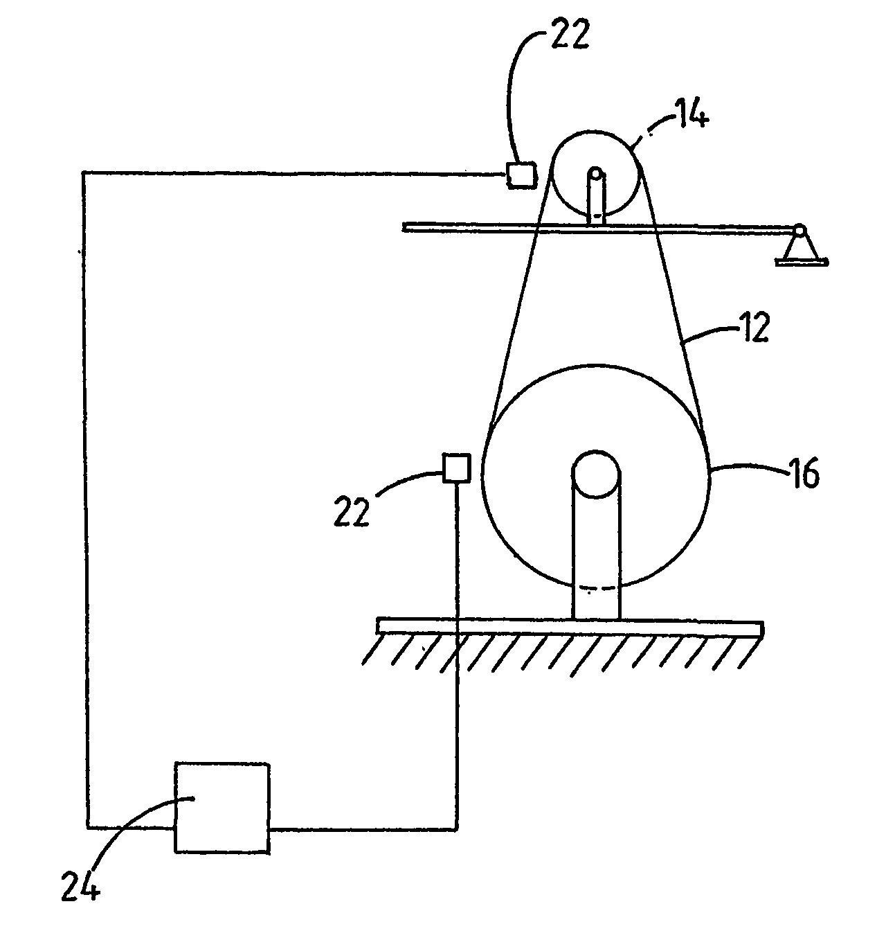
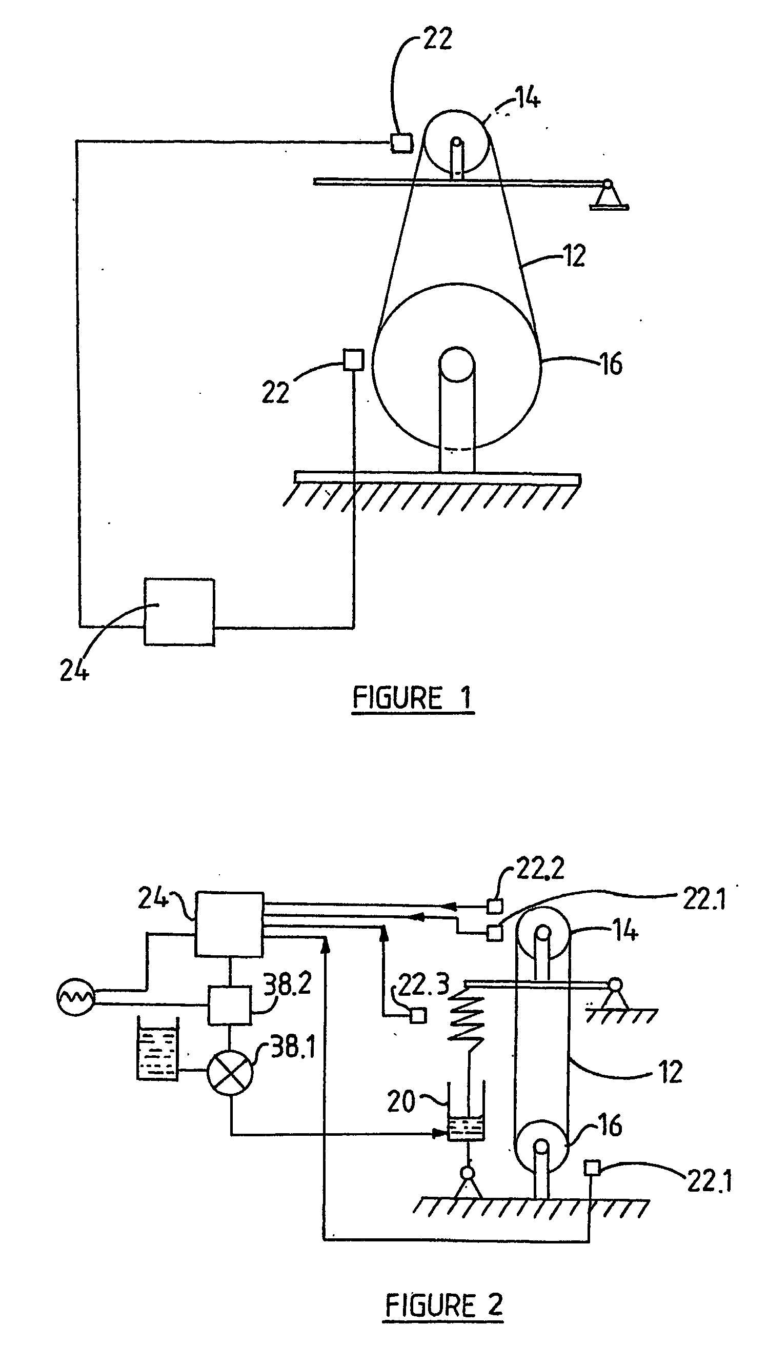
[0043] FIG. 1 is a diagrammatical illustration of a guide system according to one embodiment of the invention;

[0044] FIG. 2 is a diagrammatical illustration of a guide system according to another embodiment of the invention, wherein the guide system includes electronic control means;

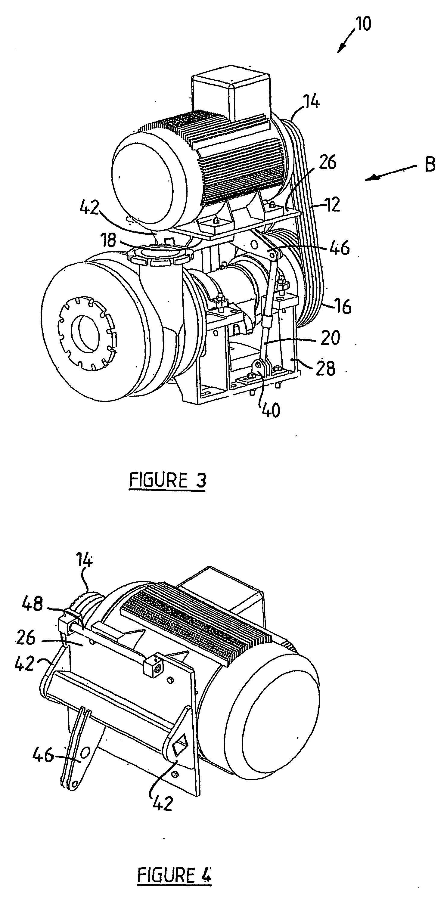
[0045] FIG. 3 is an perspective view of the guide system of the Invention;

[0046] FIG. 4 is a perspective view from below of a portion of the guide system of FIG. 3;

[0047] FIG. 5 is a perspective view of a tensioning means and regulating arm of the guide system of FIG. 3; and

[0048] FIGS. 6 to 8 are side views, in the direction of arrow A of FIG. 3 of various operating positions of the guide system, illustrating working of the same.

[0049] A guide system according to the invention is generally designated by reference numeral 10. The guide system 10 co...


PUM


Abstract

The invention provides for a guide system (10) for tensioning a belt. The guide system (10) comprises an endless belt (12); at least two guides (14, 16) for guiding the belt (12); and tensioning means (18) for tensioning the belt (12) between the guides (14, 16), the tensioning means (18) being movable between a tensioned and a substantially non-tensioned position such that in the tensioned position it is biased to the non-tensioned position to compensate for a loss in belt tension. The guide system (10) also comprises self-adjusting regulating means that is operatively associated with the tensioning means (18) and that is adapted for moving the tensioning means (18) towards its tensioned position upon occurrence of belt slacking for effecting substantially immediate tensioning of the belt (12) while the belt (12) is running and without the necessity of manual intervention. The invention further includes a method of regulating belt tension of the belt (12) and for effecting tensioning of the belt (12) upon occurrence of belt slacking.

Description

[0001] This invention relates to a guide system. More particularly, the invention concerns a guide system adapted for tensioning a belt extending between adjacent guides of the guide system. The invention also includes a method of regulating belt tension of the belt and for effecting tensioning of the belt upon occurrence of belt slacking.[0002] Those who are familiar with the Industry will appreciate that mechanical power transmission systems for driving pumps, crushers, floatation cells and the like often comprise driving means, such as an electrical motor including a driver pulley, and driven means, such as a driven pulley that is connected to the pump, crusher, floatation cell or the like to be driven. The driver and driven pulleys are operatively associated with one another by means of at least one intermediate belt extending between the pulleys for transmitting mechanical power from the driver to the driven pulley. It is an essential requirement for proper working of the syste...

Claims


Application Information

Patent Timeline
Patent Type & Authority Applications(United States)
IPC IPC(8): F16H7/08F16H7/14
CPCF16H7/14F16H2007/0812F16H2007/0861F16H2342/044F16H2007/0885F16H2007/0887F16H2007/0893F16H2007/0882
Inventor MARE, PHILLIPPUSSEVENSTER, CONRAD
Owner OSCILLATING SYST
Why Eureka
Try Eureka