Belt-drive system driven by internal combustion engine mounted on automotive vehicle

a technology of internal combustion engine and belt drive, which is applied in the direction of engine starters, electric generator control, gearing, etc., can solve the problems of undesirable noise, belt damage, and large fluctuation, and achieve the effect of suppressing the increase in the rotational speed of the engine, large generation torque, and quick attenuation of the amount of field curren

Inactive Publication Date: 2006-03-14
DENSO CORP
View PDF11 Cites 7 Cited by
  • Summary
  • Abstract
  • Description
  • Claims
  • Application Information

AI Technical Summary

Benefits of technology

[0018]Under a condition where an average rotational speed ωa of a rotor of the first generator is lower than a predetermined rotational speed ω0 (for example, an idling speed), a generation torque of the first generator is controlled. That is, when an instantaneous rotational speed ω of the rotor is higher than its average speed ωa, a large amount of current is supplied to a field coil of the rotor to thereby generate a large generation torque. The generation torque suppresses increase in the rotational speed of the engine. On the other hand, when the instantaneous rotational speed ω is lower than the average rotational speed ωa, the field current is circulated in a closed circuit to quickly attenuate the amount of the field current and to thereby suppress decrease in the rotational speed of the engine. Thus, the fluctuations in the rotational speed of the engine are suppressed, and thereby the fluctuations in the belt tension are reduced. Under a condition where the average rotational speed ωa is higher than the predetermined speed ω0, the first generator is controlled in a usual manner for supplying electric power to the loads.
[0019]Preferably, the first generator is positioned in the belt-drive system at a position closer to the belt-tensioner pulley than the second generator is positioned. In this manner, the fluctuations in the belt tension are more effectively reduced. An amount of swing in the belt-tensioner may be detected, and the generation torque of the first generator may be controlled when the amount of swing exceeds a predetermined level.

Problems solved by technology

The fluctuations are especially large when the engine operation is unstable at a low speed.
If the fluctuations in the belt tension are large, the belt would be damaged and undesirable noise would be generated.

Method used


Image

  • Belt-drive system driven by internal combustion engine mounted on automotive vehicle
  • Belt-drive system driven by internal combustion engine mounted on automotive vehicle
  • Belt-drive system driven by internal combustion engine mounted on automotive vehicle

Examples


Embodiment Construction

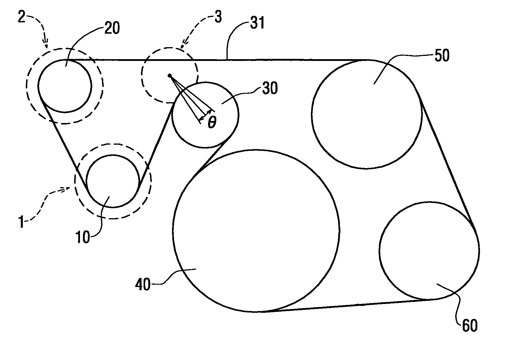
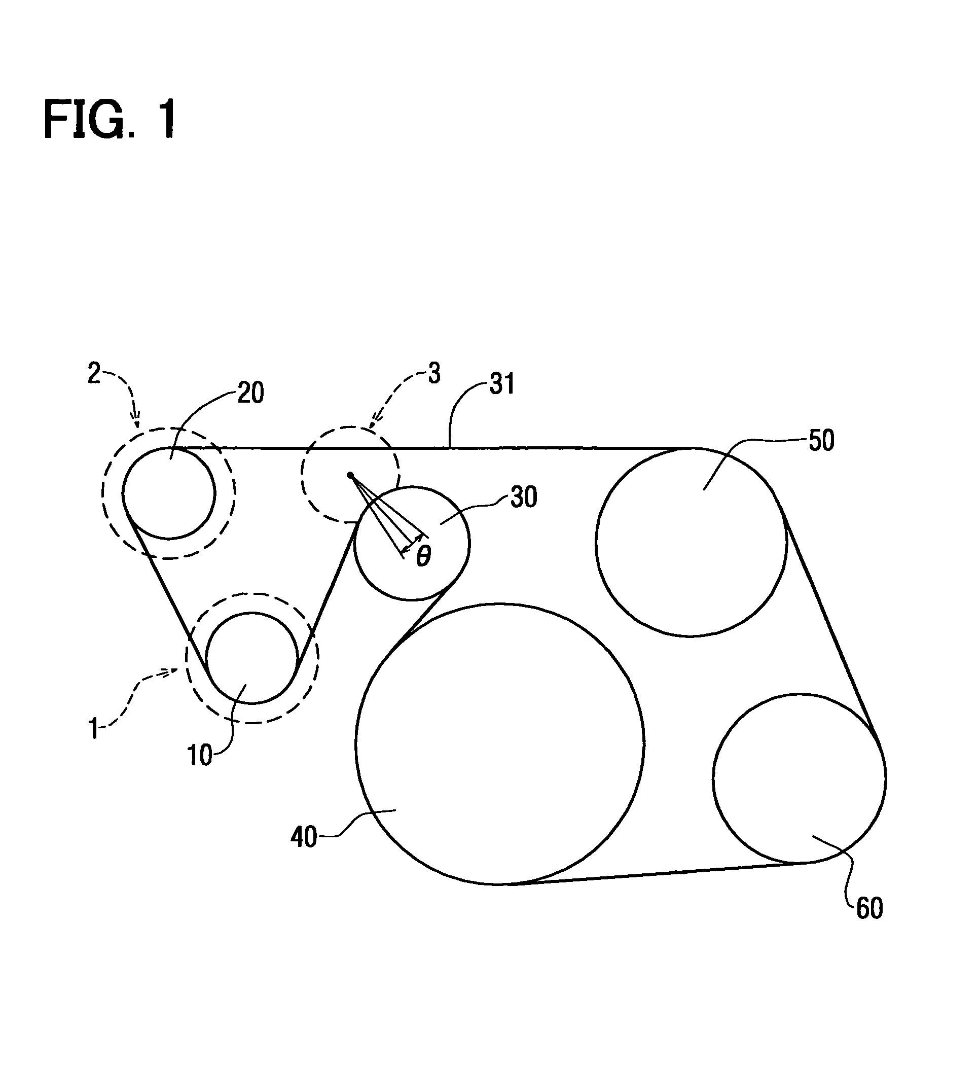
[0028]A preferred embodiment of the present invention will be described with reference to FIGS. 1–4. FIG. 1 shows a belt-drive system according to the present invention. In a conventional belt-drive system shown in FIG. 7, only one generator 2a is included in the system. In the belt-drive system shown in FIG. 1, two generators, i.e., a first generator 1 and a second generator 2 are included in the system.

[0029]A pulley 10 connected to a first generator 1, a pulley 20 connected to a second generator 2, a pulley 50 for a water cooler and a pulley 60 for a compressor of an air-conditioner are all driven by a crankshaft pulley 40 connected to an internal combustion engine through a single belt 31 wound around all the pulleys. A pulley 30 of an automatic belt tensioner 3 is also disposed in the belt-drive system for maintaining the belt tension constant.

[0030]The first generator 1 supplies electric power to a 42-volt system including a battery, while the second generator 2 supplies power...


PUM


Abstract

A generator for alleviating fluctuations in instantaneous rotational speed of an internal combustion engine is included in a belt-drive system. When an average rotational speed of the generator is lower than a predetermined speed, for example, an idling speed, a generation torque of the generator is controlled to reduce the belt tension fluctuations. When the average speed of the generator is higher than the predetermined speed, the generator is controlled in a usual manner to supply a stable power to the electric loads.

Description

CROSS-REFERENCE TO RELATED APPLICATION[0001]This application is based upon and claims benefit of priority of Japanese Patent Application No. 2002-292266 filed on Oct. 4, 2002, the content of which is incorporated herein by reference.BACKGROUND OF THE INVENTION[0002]1. Field of the Invention[0003]The present invention relates to a belt-drive system for driving auxiliary devices mounted on an automotive vehicle.[0004]2. Description of Related Art[0005]In a recent automotive vehicle, a space available for an engine compartment is getting smaller in order to secure a sufficient space for a passenger compartment. To minimize a space occupied by a belt-drive system for driving various auxiliary devices including a generator, a so-called serpentine belt-drive system that drives all the auxiliary devices with a single belt is becoming popular. An example of such a serpentine belt-drive system is shown in FIG. 7. A single driving belt 31 is wound around a crankshaft pulley 40 connected to an...

Claims


Application Information

Patent Timeline
Patent Type & Authority Patents(United States)
IPC IPC(8): F16H63/28F02N11/04H02K7/18F02B67/06F16H7/12H02P9/04H02P9/14H02P9/30
CPCF02B67/06F16H7/1281F16H2007/0861
Inventor NAKAMURA, SHIGENOBU
Owner DENSO CORP
Why Eureka
Try Eureka