

Porous object based on silicon carbide and process for producing the same
a silicon carbide and porous material technology, applied in the field of silicon carbidebased porous material, can solve the problems of low firing yield, large amount of pore formers to be added, low strength of resultant filter, etc., and achieve the effect of reducing the generation of large pores, increasing the porousity, and maintaining the pore diameter
- Summary
- Abstract
- Description
- Claims
- Application Information
AI Technical Summary
Benefits of technology
Problems solved by technology
Method used
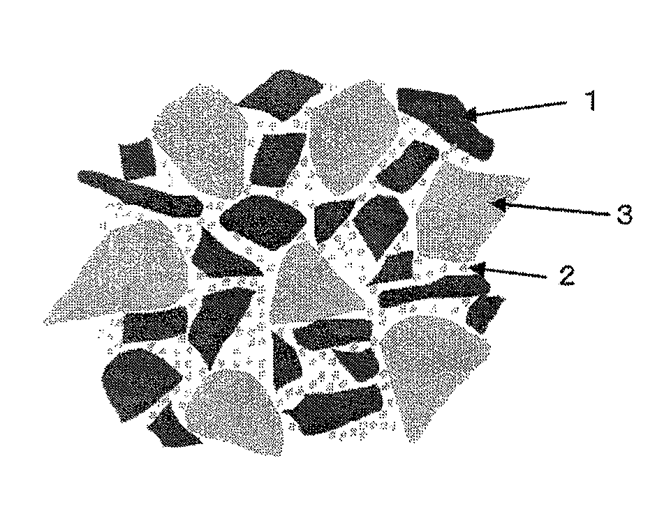
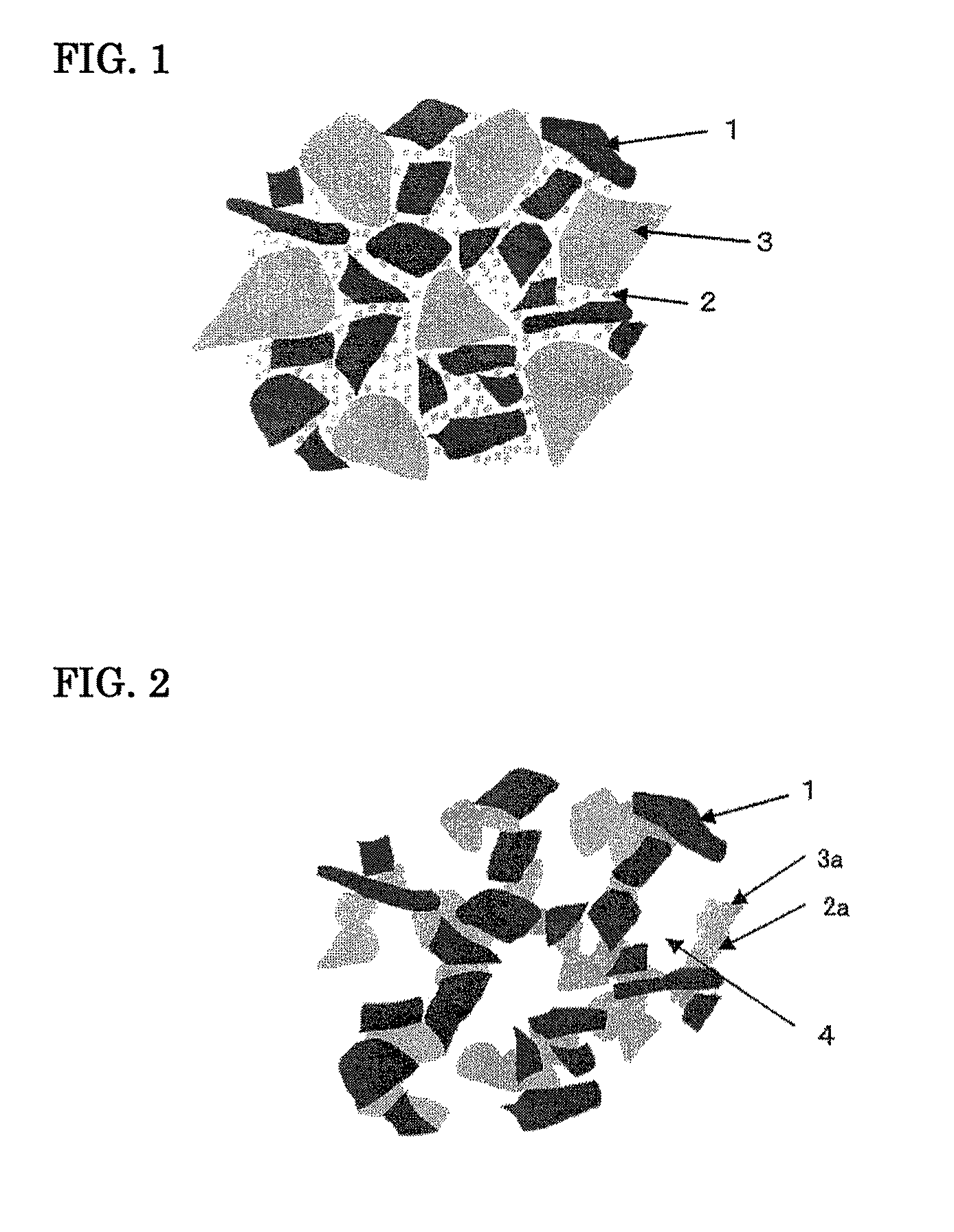
Image

Examples
example 1
[0057]A SiC raw material powder and a Si powder having an average particle diameter of 5 μm were compounded for the composition to be 80:20 by mass, to the resultant powder of 100 parts by mass was added 15 parts by mass of a resin type silicone resin particle having an average particle diameter of 12 μm (composition: (CH3SiO1.5)n; other characteristics are also shown in Table 1). Then, 6 parts by mass of methyl cellulose as organic binder, 2.5 parts by mass of surfactant and 24 parts by mass of water were added there to, uniformly mixed and kneaded to give a clay for forming. The resultant clay was formed by an extruder, dried to give a silicon carbide-based porous article having a partition wall thickness of 310 μm, a cell density of about 46.5 cells / cm2 (300 cells / in.2), regular tetragon in section of one side of 35 mm and a length of 152 mm. The green body of silicon carbide-based porous article was plugged in both end faces for the end face to be a checkered pattern. Namely, th...
example 2
[0058]It was conducted in the same manner as in Example 1 except that auxiliary components (SrO, SiO2) shown in Table 1 were further added in Example 1.
example 3
[0059]It was conducted in the same manner as in Example 1 except that a resin type silicone resin particle (composition (CH3SiO1.5)n) with an average particle diameter of 2 μm was used in Example 1.
PUM
| Property | Measurement | Unit |
|---|---|---|
| pore diameter | aaaaa | aaaaa |
| porosity | aaaaa | aaaaa |
| tap density | aaaaa | aaaaa |
Abstract
Description
Claims
Application Information