Integrated turbine power generation system with catalytic reactor

a technology of integrated turbines and primary reactors, which is applied in the direction of electric generator control, machines/engines, mechanical equipment, etc., can solve the problems of limited efficiency of conventional integrated turbogenerator systems using flame-based or catalytic primary reactors, emissions problems, and failure to maintain a steady state operating temperatur

Inactive Publication Date: 2004-05-27
CAPSTONE TURBINE
View PDF9 Cites 44 Cited by
  • Summary
  • Abstract
  • Description
  • Claims
  • Application Information

AI Technical Summary

Problems solved by technology

Conventional integrated turbogenerator systems using a flame-based or catalytic primary reactor have limited efficiency, emissions problems, do not maintain a steady state operating temperature at varying loads, and have difficulty in dealing with varying load conditions.

Method used


Image

  • Integrated turbine power generation system with catalytic reactor
  • Integrated turbine power generation system with catalytic reactor
  • Integrated turbine power generation system with catalytic reactor

Examples


Embodiment Construction

)

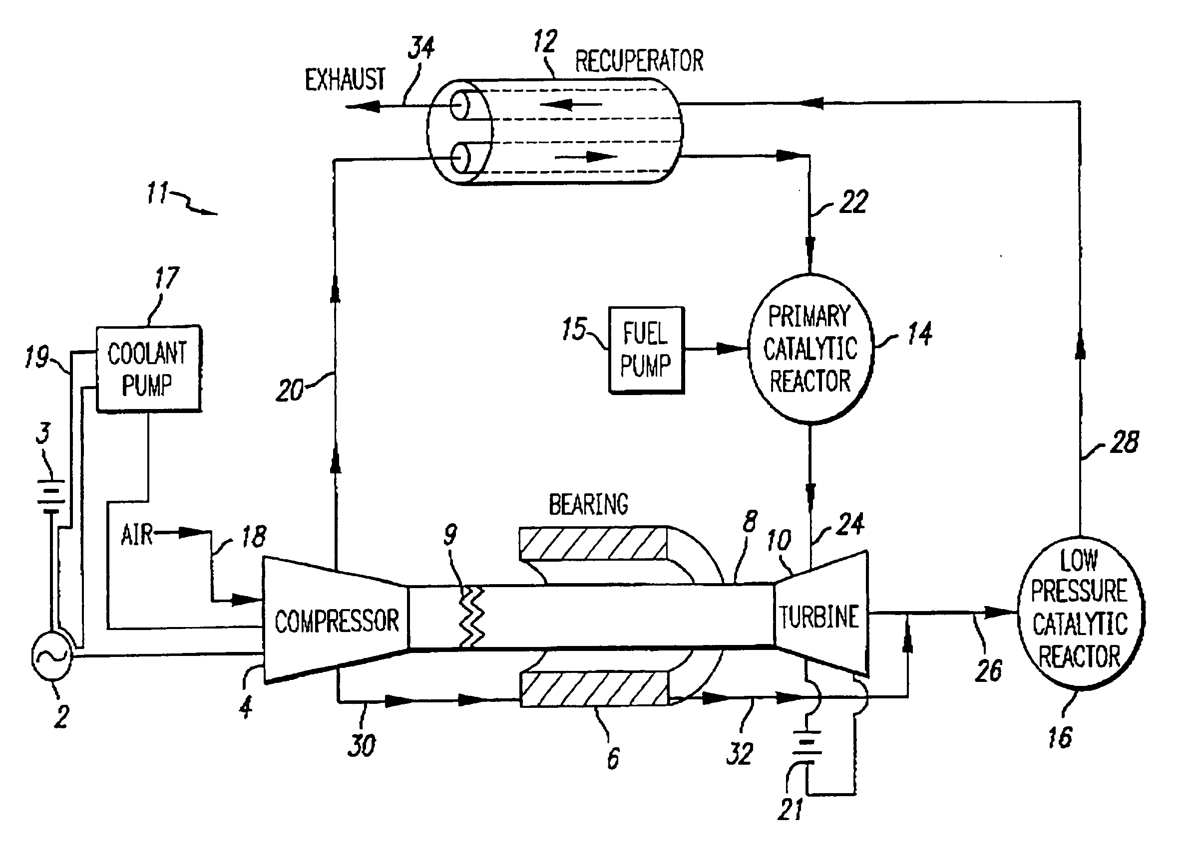
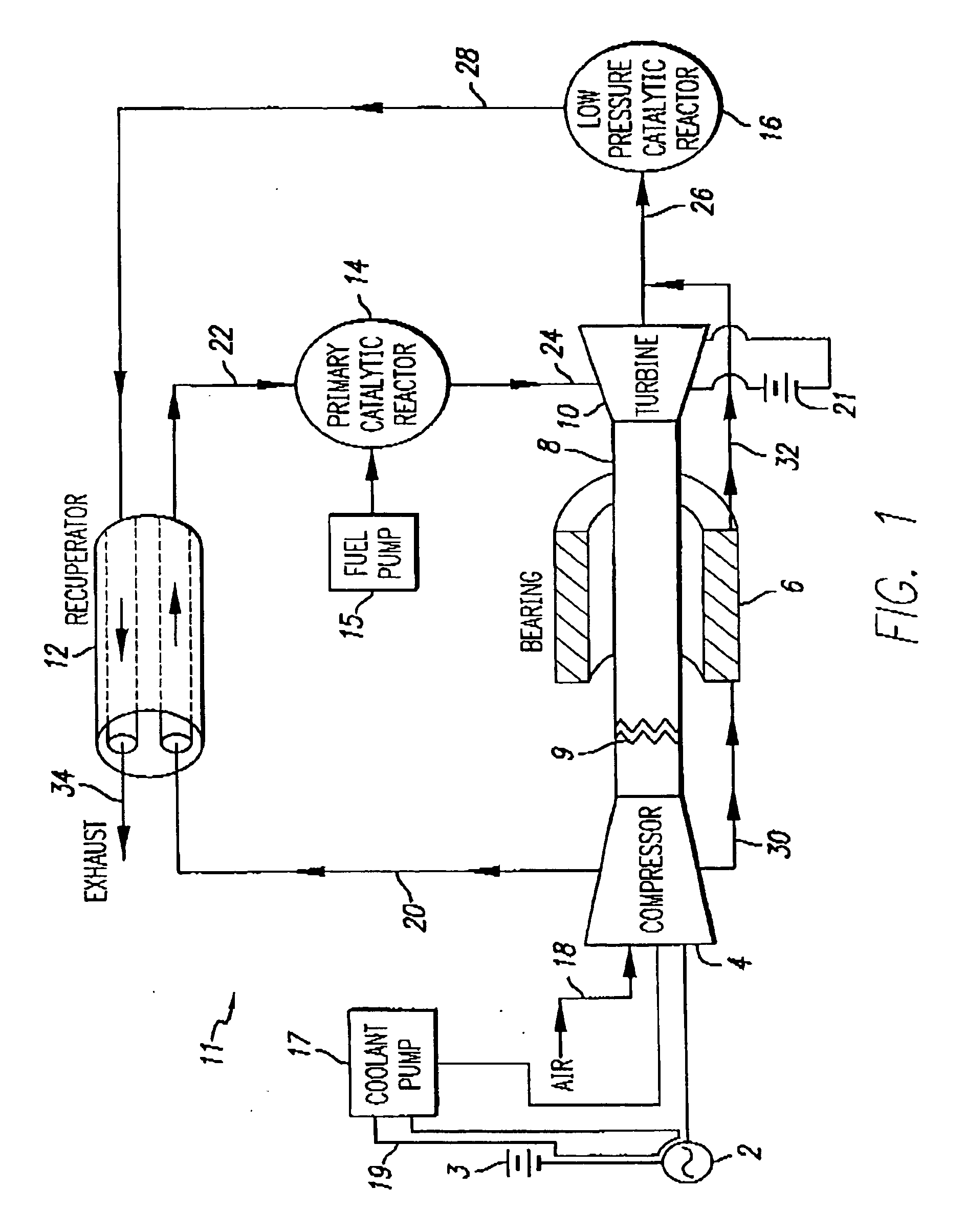
[0138] FIG. 1 illustrates a preferred integrated turbine power generation system in block diagram form. The system 11 is useful for many applications including cogeneration and as a power source for vehicles. System 11 preferably converts chemical energy, from fuels such as natural gas or gasoline, into mechanical power, electrical power and / or thermal energy. One preferred embodiment of system 11 includes a compressor 4 for compressing gas entering system 11 through line 18. The gas entering through line 18 can be air, or alternatively can be air mixed with fuel. Compressor 4 causes the gas to flow along line 20 to, and through, a heat exchanger, preferably a recuperator 12. As discussed in further detail below, the gas is heated during its passage through the recuperator 12, ideally by counter flowing heated exhaust gas that enters recuperator 12 along line 28 as the gas approaches its exit to system 11 through line 34. Once heated, the compressed gas flows onward along line 22 i...


PUM


Abstract

The invention provides integrated turbogenerators having a turbine wheel, a compressor impeller, and a motor generator mounted to or mechanically constrained to a common shaft, and improved components and configurations thereof.

Description

[0001] This application is a division of U.S. patent application Ser. No. 09 / 933,663, filed Aug. 22, 2001, which is a continuation-in-part of U.S. patent application Ser. No. 09 / 207,817, filed Dec. 8, 1998 (now U.S. Pat. No. 6,487,096), which claims the benefit of U.S. provisional application serial No. 60 / 080,457, filed Apr. 2, 1998, and which is a continuation-in-part of U.S. patent application Ser. No. 09 / 772,537, filed on Jan. 29, 2001 (now U.S. Pat. No. 6,381,944), which is a continuation of U.S. patent application Ser. No. 09 / 420,494, filed on Oct. 19, 1999 (now U.S. Pat. No. 6,192,668), all of which are incorporated herein by reference in their entirety as set forth below in full.[0002] 1. Field of the Invention[0003] This invention relates to integrated turbogenerators for producing power under varying load conditions, and more specifically to the use of catalytic reactors in combination with such systems.[0004] 2. Description of the Related Art[0005] Integrated turbogenerat...

Claims


Application Information

Patent Timeline
Patent Type & Authority Applications(United States)
IPC IPC(8): F02C3/22F02C7/236H02J1/10H02J1/14
CPCF02C3/22F02C7/2365Y02E20/14H02J1/14H02J1/10
Inventor WILLIS, JEFFREY W.BERNER, PAULPONT, GUILLERMOWACKNOV, JOEL
Owner CAPSTONE TURBINE
Why Eureka
Try Eureka