Coaxial connector and ground pad that mounts said coaxial connector

a coaxial connector and ground pad technology, applied in the direction of fixed connections, two-pole connections, coupling device connections, etc., can solve the problems of ground terminals peeling off of ground pads, cellular phones and laptop computers becoming increasingly smaller and densely equipped with so many parts,

Inactive Publication Date: 2004-05-27
HONDA TSUSHIN IND
View PDF9 Cites 81 Cited by
  • Summary
  • Abstract
  • Description
  • Claims
  • Application Information

AI Technical Summary

Problems solved by technology

In recent years, electronic devices such as cellular phones and laptop computers have increasingly become smaller and very densely equipped with so many parts.
In said patent application 2002-95985, although grounding capacity is to be improved by means of providing at least three ground terminals to be grounded on ground pads that are installed on the circuit board on or near the circle whose center is the center of the shell, there is such a problem that, because the corners of the ground terminals are like sharp edges having acute angles or right angles, when thrust is exerted on the coaxial connector, these corners may easily get peeled off and, from there, the ground terminals may peel off of the ground pads.
On the other hand, by means of making the whole of the bottom surface of the shell substantially be a ground terminal instead of providing protruding ground terminals and by means of connecting these ground terminals with the ground pad that has been installed on the circuit board, the grounding capacity is to be improved; however, in this case, there is such a problem that although the whole of the bottom surface of the shell is tin soldered, due to the surface tension of the soldered tin, the coaxial connector may float and that may hinder the coaxial connector from being mounted on the circuit board.
Furthermore, there is such a problem that if one places a signal terminal outer to the outside of the shell, then that leads to the lengthening of the terminal section and in turn causes the lengthening of the electronic length.
Moreover, there is such a problem that, because conventional ground pads that are installed on the circuit boards and on which Surface Mounting Technology type coaxial connector gets mounted are, as shown in FIG. 14(c), provided separately in two places, right and left, depending on the connection, grounding may become unstable.
Furthermore, there is such a problem that because the ground pads are installed separately in more than two locations, the total bottom surface area of the ground pads are small and, because the corners have acute angles, peeling off may start from these corners.

Method used


Image

  • Coaxial connector and ground pad that mounts said coaxial connector
  • Coaxial connector and ground pad that mounts said coaxial connector
  • Coaxial connector and ground pad that mounts said coaxial connector

Examples


second embodiment

[0033] Next, FIGS. 6 through 8 indicate the coaxial connector in the present invention. FIG. 6 is its plan view, FIG. 7 is its side view and FIG. 8 is its bottom plan view.

[0034] The featured coaxial connector 1 is, just like said coaxial connector 1, a Surface Mounting Technology (SMT) type female coaxial connector and is mounted on the surface of the circuit board 3. The coaxial connector 1 is comprised of a contact 13, an insulator 17 made of synthetic resin that holds the contact 13 and a metallic shell 11 that contains the insulator 17. As for the contact 13 and insulator 17, they have the substantially same features as said coaxial connector 1 and their explanations for are omitted.

[0035] The whole of the bottom surface of the shell 11 in the present embodiment is a ground terminal 22 that connects and grounds with the ground pad 30 of the circuit board 3 and there are cuts 12 with certain intervals in between. The depth of the cuts 12 is designed to be approximately the same ...

third embodiment

[0036] Next, FIG. 9 indicates a cross-sectional view of the present invention.

[0037] The featured coaxial connector 1 is, just like said coaxial connectors 1, a Surface Mounting Technology (SMT) type female connector and is mounted on the surface of the circuit board 3. This coaxial connector 1 is comprised of a contact 13, an insulator 17 made of synthetic resin that holds the contact 13, and a metallic shell 11 that contains the insulator 17 and that has first ground terminals 20, 20 and second ground terminals 21. The shell 11 and insulator 17 have the substantially same features as said coaxial connector 1 and their explanations are omitted.

[0038] The contact 13 of the coaxial connector in the present embodiment is, as shown by FIGS. 10 and 11, provided with the terminal section 15 that substantially horizontally extends across the central bottom section and this terminal section 15 has such length that it can be contained within the insulator 17. Then, on the bottom of the term...

first embodiment

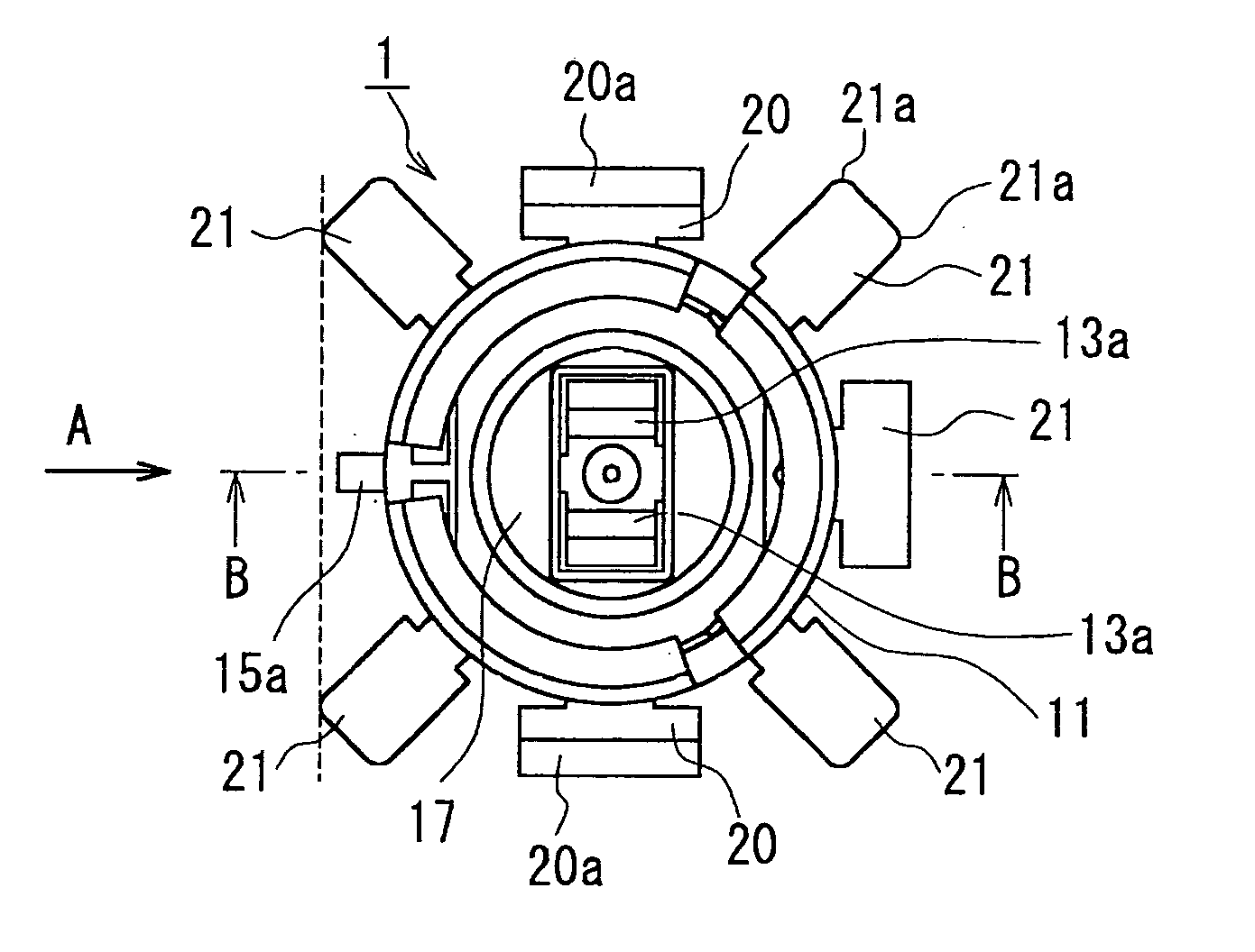
[0045] [FIG. 1] A plan view of the present invention.

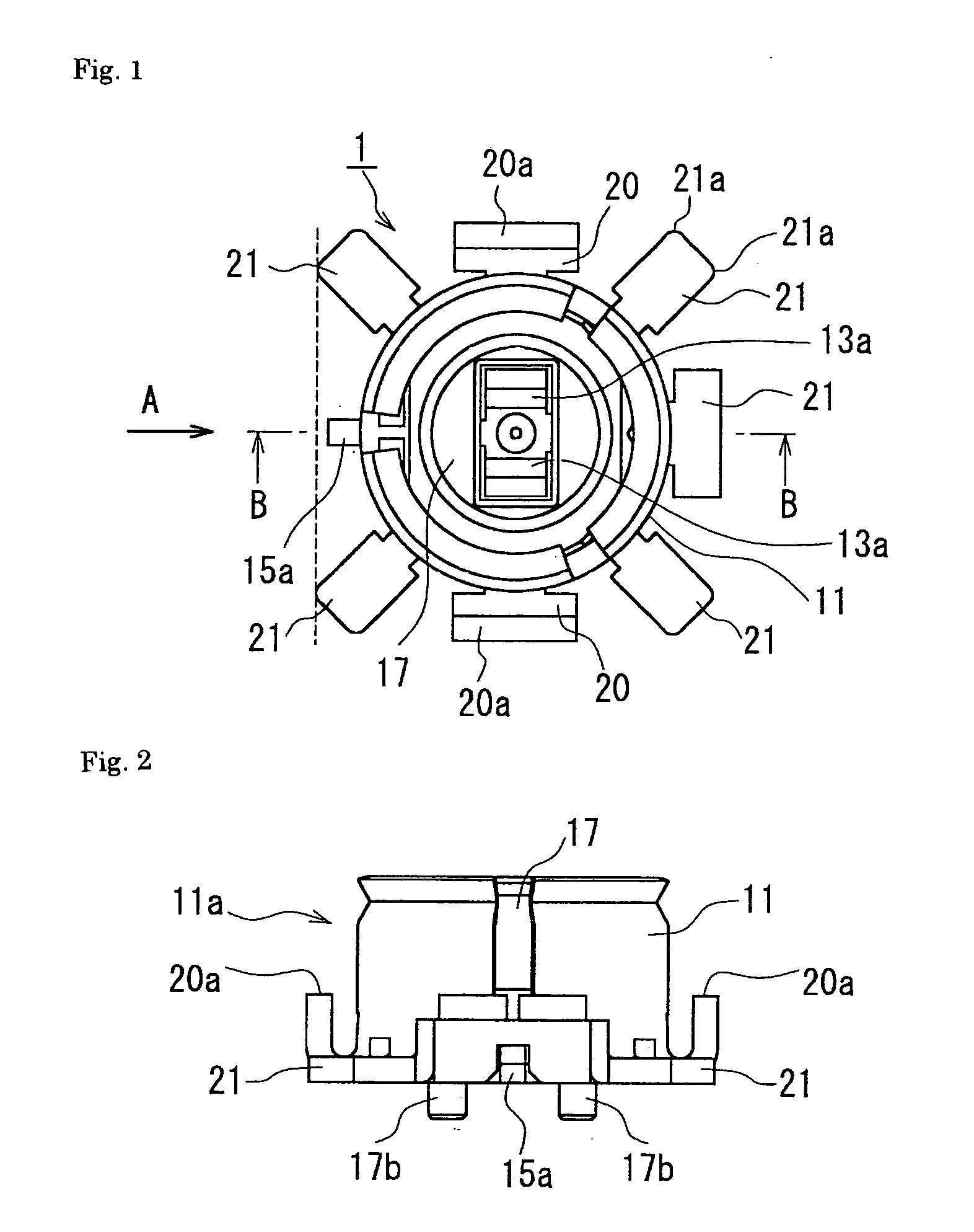
[0046] [FIG. 2] A side view of the coaxial connector as seen from the direction of Arrow A of FIG. 1.

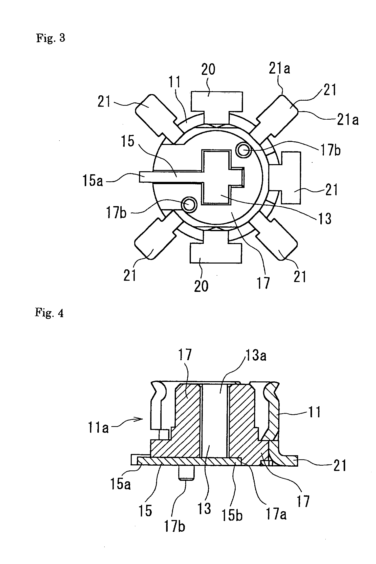
[0047] [FIG. 3] A bottom plan view of the first embodiment of the present invention of FIG. 1.

[0048] [FIG. 4] A cross-sectional view of the coaxial connector along the line B-B of FIG. 1.

[0049] [FIG. 5] A side cross-sectional view of the coaxial connector being connected with a corresponding connector.

[0050] [FIG. 6] A plan view of the second embodiment of the present invention.

[0051] [FIG. 7] A side view of the coaxial connector of FIG. 6.

[0052] [FIG. 8] A bottom plan view of the coaxial connector of FIG. 6.

[0053] [FIG. 9] A cross-sectional view of the coaxial connector of the third embodiment.

[0054] [FIG. 10] A front view of the contact of the coaxial connector of the third embodiment.

[0055] [FIG. 11] A side view of the contact of FIG. 10.

[0056] [FIG. 12] A plan view that shows the form of a ground pad and pad

[0057] [FIG. 13] A p...


PUM


Abstract

A coaxial connector has improved grounding capacity for high frequency waves improved resistance against the peeling off of grounding terminals from ground pads and ground pads that mount the coaxial connectors and that have improved resistance against the peeling off of the ground pads from the circuit board. In the coaxial connector, corners 21a of ground terminals 21 that ground on ground pads 30 installed on circuit board 3 are characterized in that they are obtusely beveled or rounded, and the ground pad 30 that mounts the coaxial connector 1 is characterized in that it has a substantially square or U shape.

Description

[0001] The present invention relates to coaxial connectors and ground pads that mount said coaxial connectors.PRIOR ART[0002] In recent years, electronic devices such as cellular phones and laptop computers have increasingly become smaller and very densely equipped with so many parts. For example, an ordinary coaxial connector 100 that uses Surface Mounting Technology (SMT) shown in FIGS. 14(a) and 14(b) is a female coaxial connector and is comprised of a contact 103 that comes into contact with and is electronically connected with a contact of a corresponding male connector (not shown), an insulator 107 that holds the contact 103 and a metallic shell 101 that contains the insulator 107. A shell 101 has a substantially cylindrical-shaped connecting section 101a that connects with a corresponding male connector and, in the near center location of the connecting section 101a, a contact 103 is locating. The contact 103 that has tips that are substantially U shaped, two-forked contact s...

Claims


Application Information

Patent Timeline
Patent Type & Authority Applications(United States)
CPCH01R12/57H01R12/7082H01R2103/00H01R24/50H01R2201/16
Inventor WATANABE, SHINJI
Owner HONDA TSUSHIN IND
Why Eureka
Try Eureka