Retrofit kit for interconnect cabling system

a cabling system and retrofit technology, applied in data switching networks, coupling device connections, instruments, etc., can solve the problems of patch panel monitoring and management, manual update, and inability to monitor the status of connectivity,

Inactive Publication Date: 2006-12-26
RIT TECHNOLOGIES
View PDF11 Cites 189 Cited by
  • Summary
  • Abstract
  • Description
  • Claims
  • Application Information

AI Technical Summary

Problems solved by technology

Cabling systems that include patch panels, such as patch panel 37, are problematic in terms of tracking their connectivity status, since they do not provide means, such as (scanning) wires and electrical contacts, for allowing a Scanning System to forward SSIGs via the connected patch cords, and, thereby, to obtain data associated with their connectivity status.
Consequently, the problematic patch panels cannot be monitored nor managed, which causes several forthcoming drawbacks whenever large interconnecting cabling systems are involved, due to the relatively high degree of randomness characterizing the physical arrangement of the connected patch cords.
A first drawback is associated with the fact that the recordation, reflecting the patch cords connectivity status, must be manually updated.
Such updating is very cumbersome and may result in erroneous connectivity recordation.
A second drawback involves manual changing of cables' connectivity.
In such cases, a person might accidentally disconnect a wrong patch cord, in which case an unintended data network would be disconnected, since normally, when there are many patch cords aggregated in relatively small area, it is difficult to associate the first end of a patch cord with its second end.
However, the system disclosed in WO 00 / 60475 suffers from a major drawback in that is associated with the external conductor wire (FIG. 1B, reference numeral 9, in the reference) that must be externally added to each one of the connecting cables.
Such movements might cause to disconnection of the external conductor.
Furthermore, in a system having already a relatively large number of interconnecting cables, adding additional conductors could make the cabling system even more difficult to handle and manage.
However, such an arrangement is provisory-like solution and implementing it requires human work that could be time-consuming.
In addition, the disclosed system is incapable of interacting with a technician whenever there is a desire to add new patch cords or to change the location of existing patch cords means.
The system described above has not provided a simple and reliable way for managing cabling systems, which offers also a way for interactive operation with a corresponding cabling system's manager.

Method used


Image

  • Retrofit kit for interconnect cabling system
  • Retrofit kit for interconnect cabling system
  • Retrofit kit for interconnect cabling system

Examples


Embodiment Construction

[0069]The invention is directed to a retrofit kit, preferably including an adapter plug, and related method for allowing managing non-manageable cabling systems. In particular, the invention is directed to a retrofit kit and method for allowing easy management of non-manageable cabling systems after replacement of connected patch cords by UPCs.

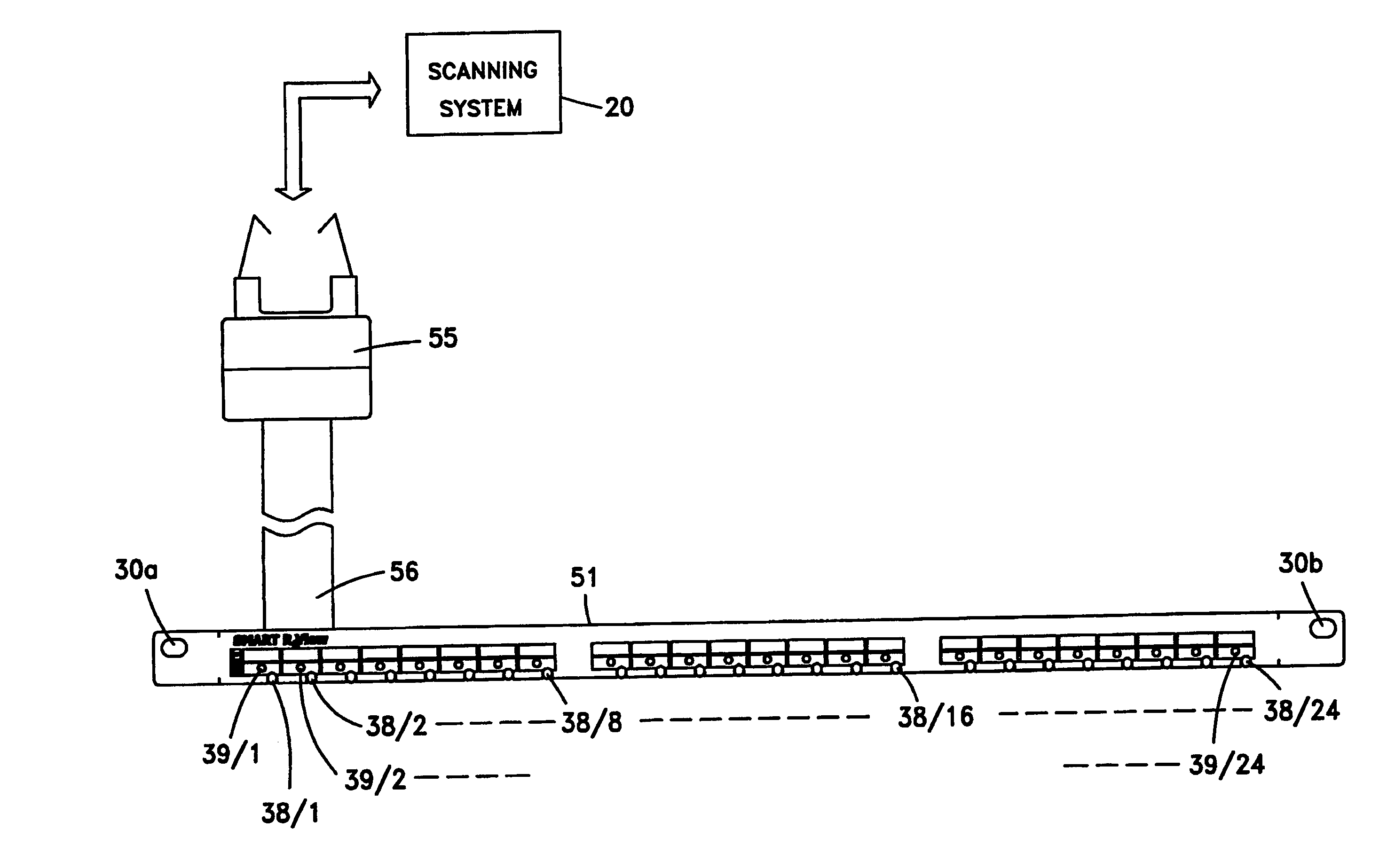
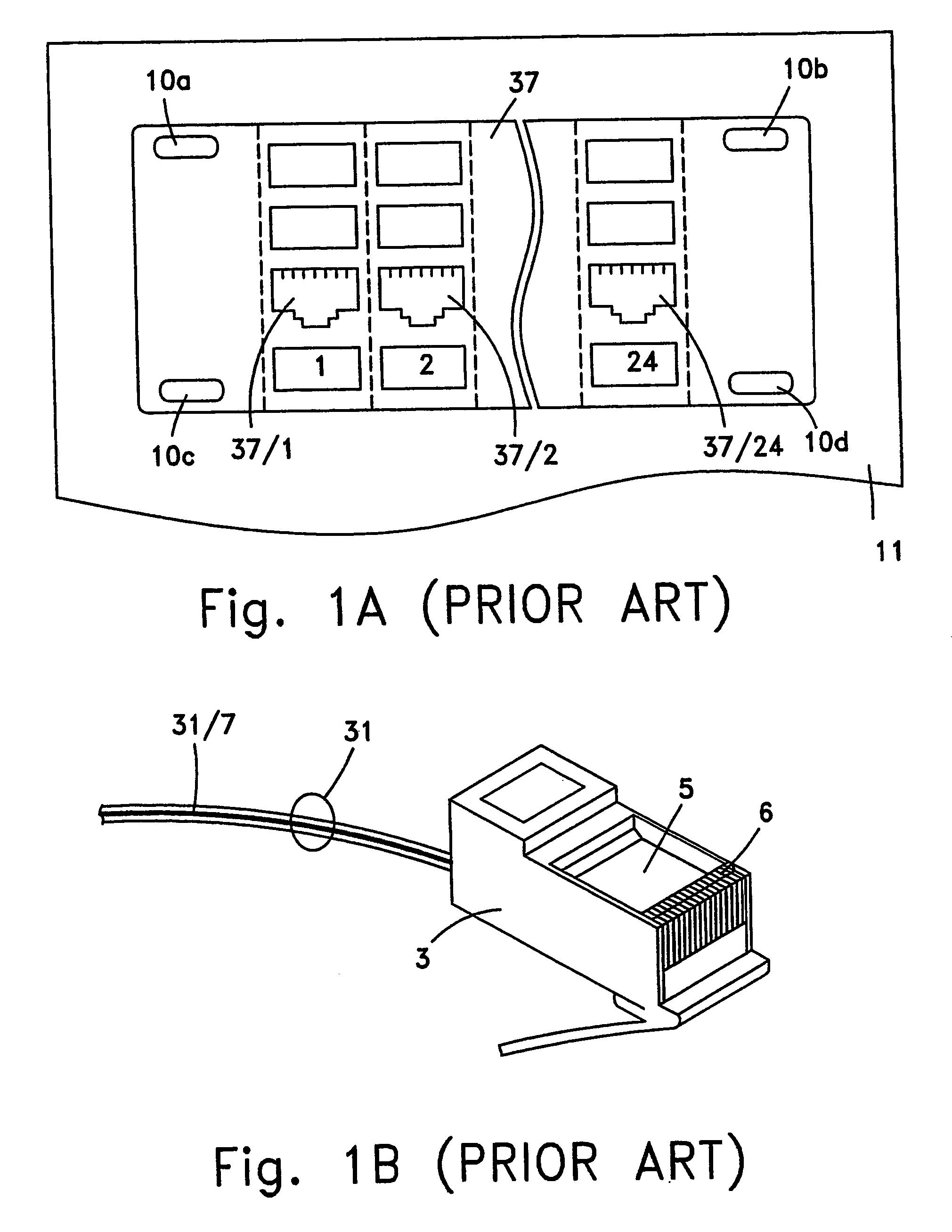
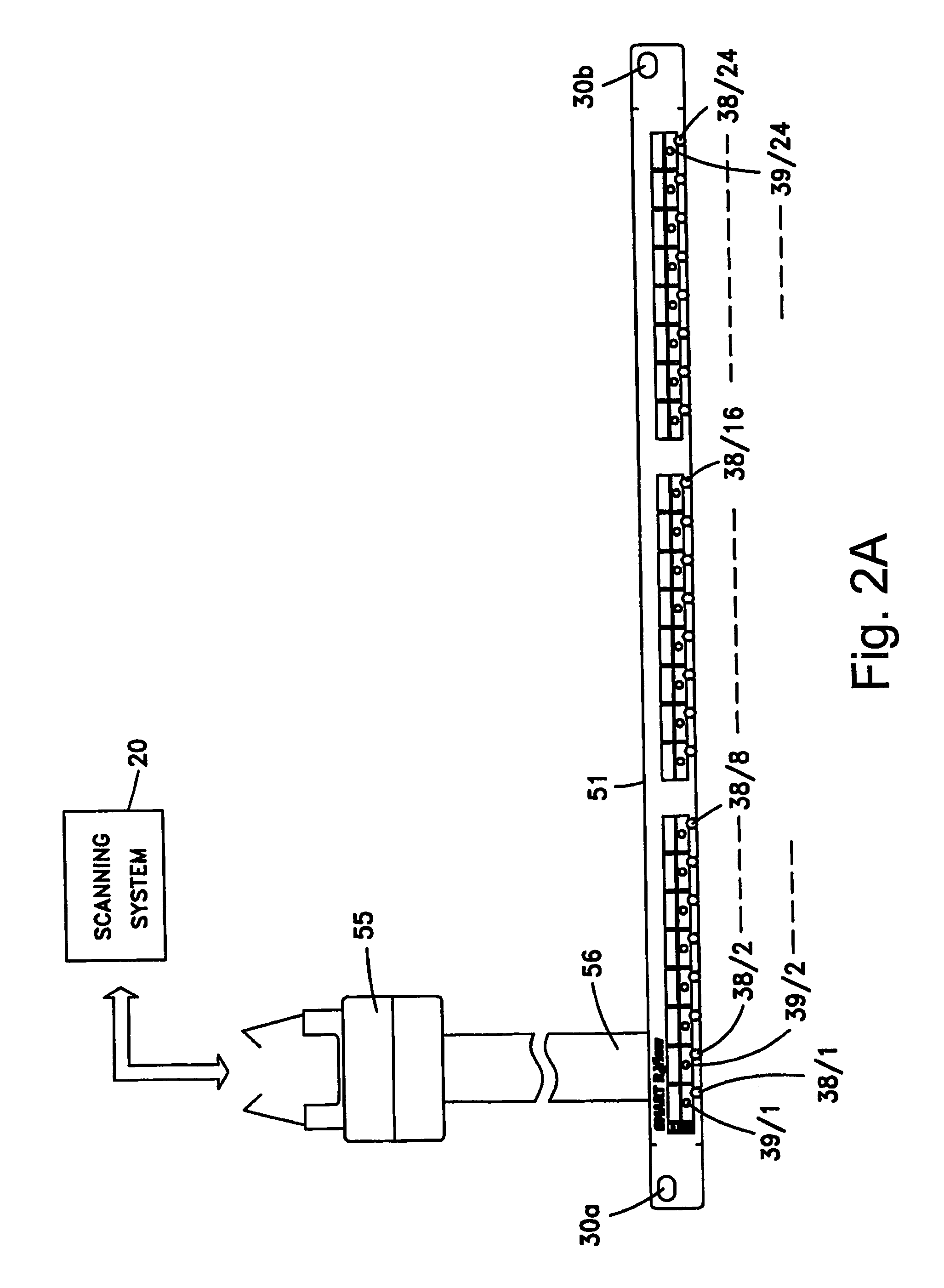
[0070]FIG. 2A schematically illustrates the front side view of an adapter panel, according to a preferred embodiment of the present invention. Adapter panel 51 comprises spring electrical contacts 38 / 1 to 38 / 24 and indication means 39 / 1 to 39 / 24 (hereinafter referred to as ‘Connectivity Status Indicators’—CSIs), each of which is associated with a corresponding socket 37 / 1 to 37 / 24 (see FIG. 1a), flat cable 56, connector 55 and two ‘holes’, 30a and 30b, for allowing mounting adapter panel 51 on patch panel 37 (FIG. 1a). Each one of spring electrical contacts 38 / 1 to 38 / 24 is intended to allow transmitting and / or receiving corresponding Scanning...


PUM

PropertyMeasurementUnit
current connectivityaaaaaaaaaa
electricalaaaaaaaaaa
transmissionaaaaaaaaaa

Abstract

System and method for automatically obtaining the connectivity status, or map, of a cabling system in data and / or voice networks are disclosed. A suitable retrofit kit for this purpose comprises a plurality of upgraded patch cords for replacement of respective used patch cords through which scanning signals are forwarded by a scanning system and a plurality of adapter panels attached to a respective patch panel that includes for a connectivity status indicator and an electrical contact for mating with the corresponding electrical scanning contact of an upgraded patch cord. Scanning signals received by an electrical contact are processed to generate data that represents the current connectivity status, or map, of the cabling system. A plurality of adapter plugs for initializing the scanning system by a first connectivity status, or map, is also provided. Cabling system management is effected with the first and current connectivity status, or map.

Description

CROSS-REFERENCE TO RELATED APPLICATIONS[0001]This application is a National Phase Application of PCT International Application No. PCT / IL2003 / 000944, International Filing Date Nov. 11, 2003, claiming priority of IL Patent No. 152768, filed Nov. 11, 2002.FIELD OF THE INVENTION[0002]The present invention relates to the field of interconnecting cabling systems of data networks. More particularly, the present invention relates to a retrofit kit and related method for allowing managing interconnecting cabling systems lacking managing capability. The present invention also relates to an adapter plug for allowing updating an existing database, or, alternatively, for generating a database, the database being associated with the management of a corresponding interconnecting cabling system.BACKGROUND OF THE INVENTION[0003]The term ‘retrofit kit’ refers to a combination of new components and / or parts and / or equipment and / or hardware, which is mechanically and / or electronically adapted to work ...

Claims


Application Information

Patent Timeline
Patent Type & Authority Patents(United States)
IPC IPC(8): H01R29/00G01R31/00G01R31/04H01RH04L12/24H04L12/26H04M3/22H04Q1/14
CPCH04L41/12H04L43/0811H04M3/229H04Q1/136H04Q1/149
Inventor SHIFRIS, PINHASHAGGAY, YAAKOV
Owner RIT TECHNOLOGIES
Why Eureka
Try Eureka