Angled patch panel with cable support bar for network cable racks

a patch panel and network cable technology, applied in the direction of casings/cabinets/drawers, coupling device connections, instruments, etc., can solve the problems of inability to provide complete bend radius control, difficult manufacturing, difficult to manage and access, etc., and achieve the effect of better cable managemen

Inactive Publication Date: 2005-03-15
PANDUIT
View PDF32 Cites 189 Cited by
  • Summary
  • Abstract
  • Description
  • Claims
  • Application Information

AI Technical Summary

Benefits of technology

It is an object of the invention to provide an improved patch panel for a network rack that can provide better cable management without the need for a horizontal cable manager.
It is another object of the invention to provide an improved patch panel that can accommodate greater port capacity.

Problems solved by technology

Many known systems are unable to provide complete bend radius control, are inefficient, are difficult to manufacture, are difficult to manage and access, and / or have other drawbacks.

Method used


Image

  • Angled patch panel with cable support bar for network cable racks
  • Angled patch panel with cable support bar for network cable racks
  • Angled patch panel with cable support bar for network cable racks

Examples


Embodiment Construction

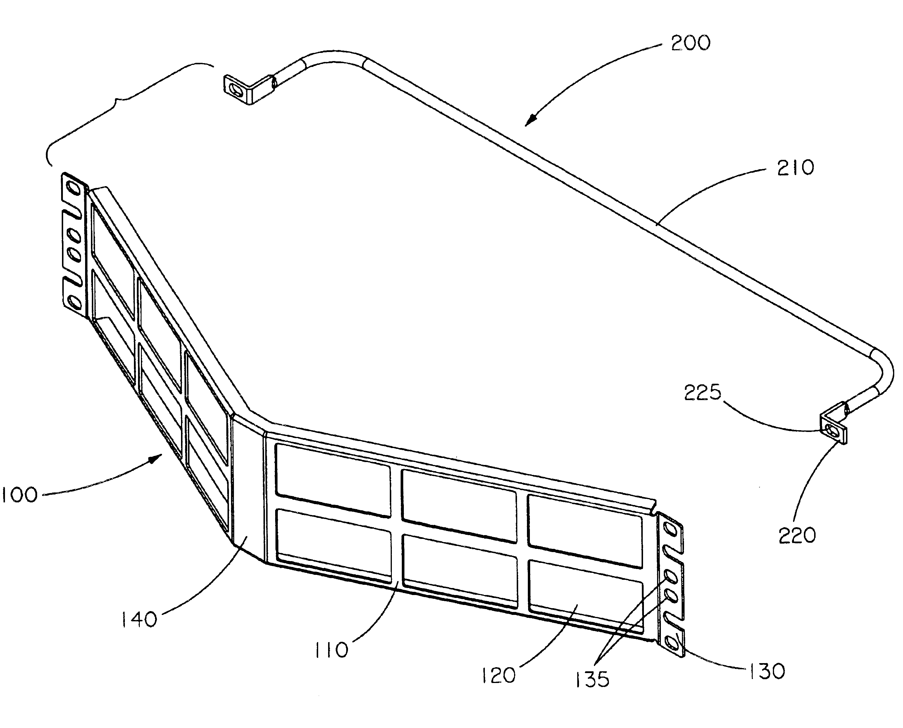
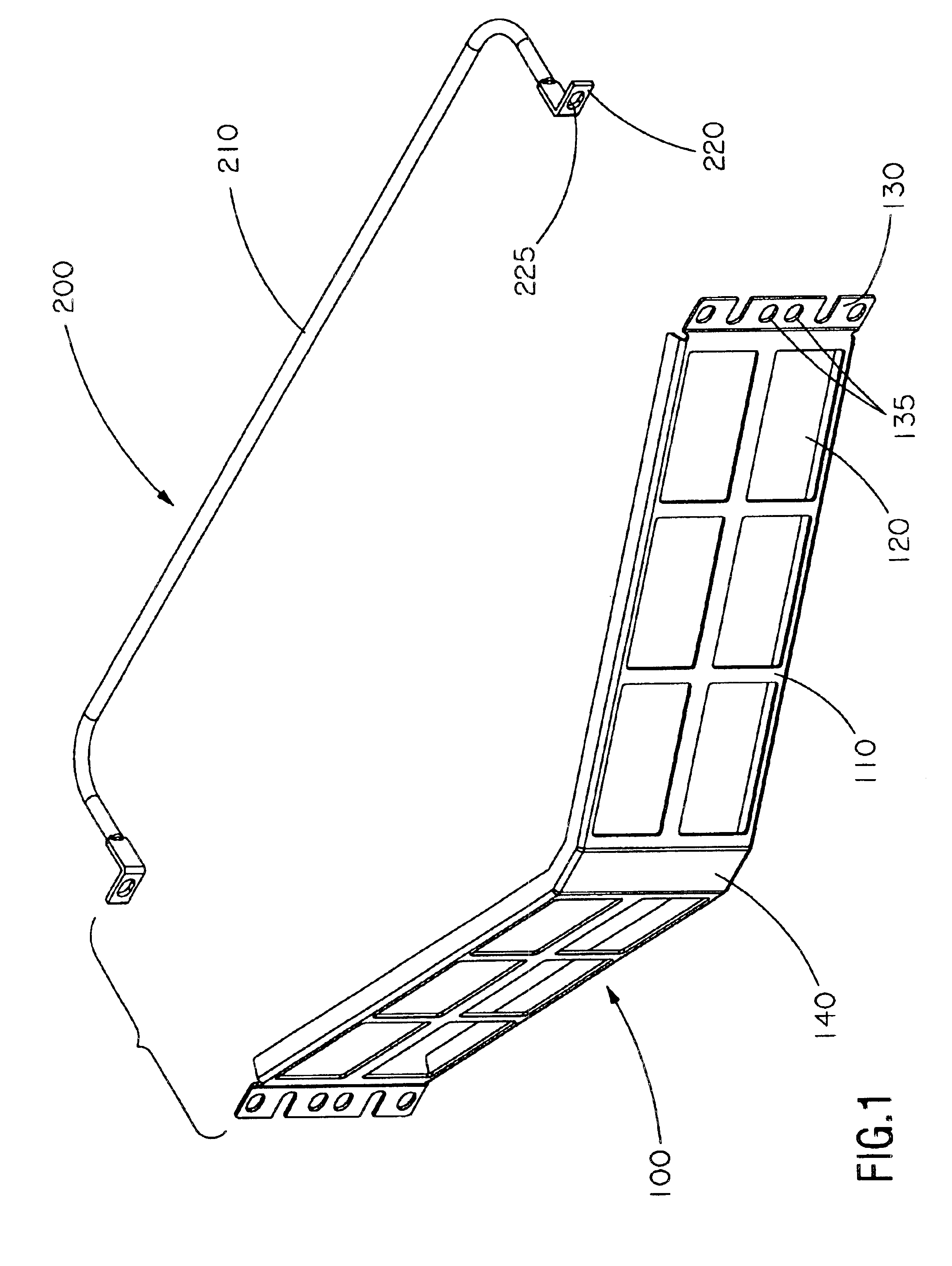
A patch panel 100 according to an exemplary first embodiment of the invention is generally shown in FIGS. 1-6 and is useful in providing a support panel for mounting reconfigurable ports for patching components in a network rack.

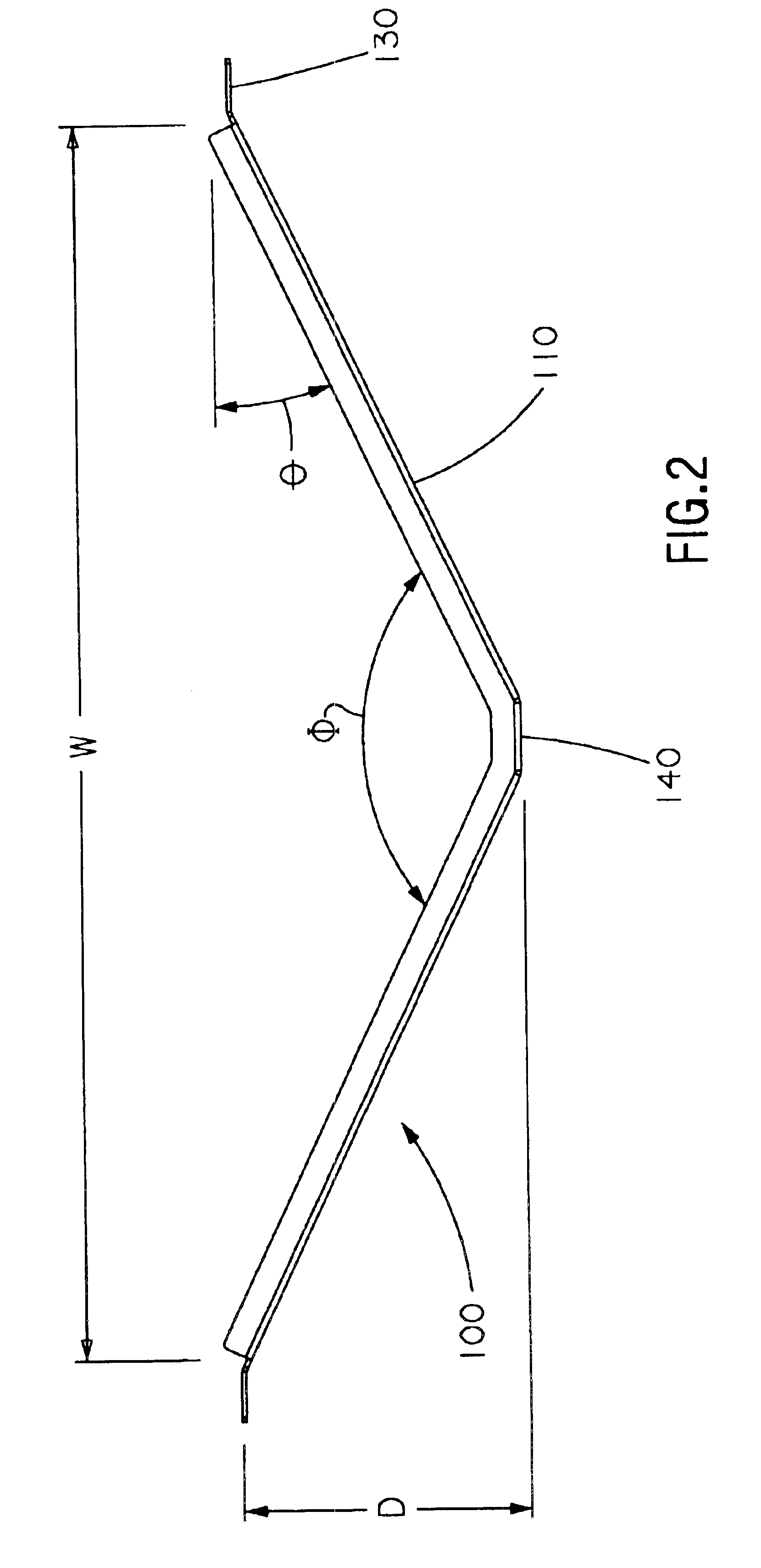
The patch panel frame 100 includes an outwardly angled central frame 110, a plurality of faceplate openings 120 and a mounting plate 130 at each end with a plurality of mounting apertures 135, as shown in FIG. 1. A flat centerpiece 140 located midway along frame 110 may be provided to space the openings 120 on opposite halves of the central frame 110 from each other. This centerpiece 140 also slightly reduces the depth D of the patch panel by eliminating the angle at a central portion where no openings 120 are located. Patch panel frame 100 is preferably formed of a suitable material, such as metal so as to be self grounding. However, frame 110 may be formed of any suitable rigid material, such as many plastics or composites. A separate or integral cable sup...


PUM


Abstract

A patch panel mountable to a network rack includes a patch panel frame and rack mounting plates. The frame forms a central section having a longitudinal width sized to fit within the network rack. The rack mounting plates are provided on opposite longitudinal ends of the central section and allow the panel to be mounted to a network rack. The central section includes two panel sections angled outwardly in an inverted V-shapes, and the central section has mounted thereon a plurality of cable connectors that receive cabling on the front side and the rear side of the patch panel frame. Each connector has a horizontal axis.

Description

BACKGROUND OF THE INVENTION1. Field of InventionGenerally, the present invention relates to cable management devices for network equipment racks. In particular, the invention relates to an angled patch panel and cable support bar therefor.2. Description of Related ArtCables, such as UTP, ScTP, coaxial and fiber optic cables, transmit data, voice, video and / or audio information in the telecommunications industry. Patch panel and network equipment enclosure rack systems are well-known in the industry. They manage and organize such cables both to and from such equipment and / or to and from such patch panels. These systems usually include the standard EIA 19″, 23″ or other distribution frame rack on which one or more patch panels, network equipment, fiber optic enclosures and the like are mounted. Rack enclosures serve various functions, including their use as slack trays, splice trays, cable organizers and patch panels. These rack enclosures also serve as interconnect or cross-connect e...

Claims


Application Information

Patent Timeline
Patent Type & Authority Patents(United States)
IPC IPC(8): G02B6/44H04Q1/02H04Q1/14H04Q1/06G02B6/46H01R13/518H01R13/60H05K5/02H05K7/18
CPCG02B6/4452H01R9/2416H01R13/518H01R13/74H04Q1/13H04Q1/068H04Q1/062H04Q1/066H04Q1/06H04Q2201/02
Inventor BARKER, JED M.DONNELL, MARK J.HONAN, KEVIN E.
Owner PANDUIT
Why Eureka
Try Eureka