Axial compression electrical connector

a technology of electrical connectors and axial compression, applied in the direction of coupling devices, coupling bases/cases, coupling devices, etc., can solve the problems of mechanical compression connections that may require compressive force levels, time-consuming and specialized tools, and special tools that may not be portable or commercially practicable for field installation us

Inactive Publication Date: 2005-09-06
ANDREW LLC
View PDF20 Cites 192 Cited by
  • Summary
  • Abstract
  • Description
  • Claims
  • Application Information

AI Technical Summary

Benefits of technology

[0036]FIGS. 5a-c show the sleeve 9 in greater detail. A cable guide surface 51 formed in the cable end 29 may be angled to assist initial insertion of the cable. A body mounting surface 53 at a connector end 17 has an inner diameter adapted to mate with the sleeve mounting surface 37 in an interference fit. A textured grip surface 55 or the like may be formed around the outer diameter of the sleeve 9 to improve the grip of a user upon the connector 1 when tightening the coupling nut 3.
[0037]The connector 1 may be pre-configured for use by assembling the components and applying limited axial compression to partially seat the interference fit surfaces together as shown in FIG. 1. This provides a user with a single assembly to handle, and removes the opportunity to misplace and or damage the individual connector 1 components.
[0042]In alternative embodiments, for example as shown in FIG. 7, like components / features numbered as above, a cable with, for example, a center conductor which has a larger diameter than the F-Type connector interface requires may be accommodated by modifying the interface 5. The interface 5 is adapted to include a center contact pin 59 held coaxially within the interface 5 by an insulator 61. Spring finger(s) 63 formed in the cable end 29 of the center contact pin 59 are biased radially inward to grasp a center conductor of the cable. To increase the inward bias, and thereby the strength of the interconnection with the center conductor, the insulator 61 supporting the center contact pin 59 may be extended towards the cable end 29 of the center contact pin 59 over a portion of the spring finger(s) 63 outer diameter.
[0045]Another embodiment, as shown in FIGS. 8a-c, like components / features numbered as above, is adapted for larger diameter cables and, for example, a standard 7 / 16 DIN connector interface. The insulator 61 supports the center contact pin 59. The insulator 61 may be preformed and press fitted into the interface 5. Alternatively, the center contact pin 59 may be temporarily supported in position and the insulator 61 formed in place by injection molding routed through injection molding entry and exit access port(s) 65 formed in the interface 5. The coupling nut 3 may be retained upon the interface 5 by deforming an outer edge of a cable end 29 facing retention groove 67 before or during the axial compression. The third gasket may be adapted to thread directly upon the outer conductor, sealing between the outer conductor and the body 7, eliminating the need for a separate sleeve component.

Problems solved by technology

Solder connections are time consuming and require specialized tools, especially during connector installation under field conditions.
Mechanical compression connections may require compressive force levels and or special tooling that may not be portable or commercially practical for field installation use.
Mechanical compression designs using wedging members compressed by tightening threads formed on the connector may be unacceptably expensive to manufacture.
In the case of a coaxial cable with a corrugated aluminum outer conductor the prior crimping may not adequately secure the desired connection because of the relative softness of the aluminum outer conductor.
Because of the difficulty with folding a solid conductor back upon itself without tearing, this form of connector is unusable with a solid metallic outer conductor coaxial cable.

Method used


Image

  • Axial compression electrical connector
  • Axial compression electrical connector
  • Axial compression electrical connector

Examples


Embodiment Construction

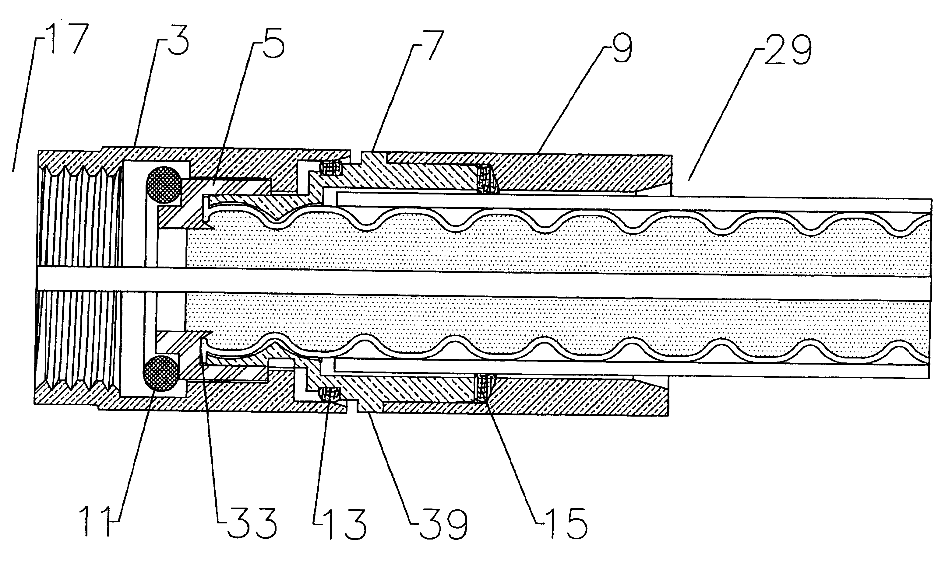
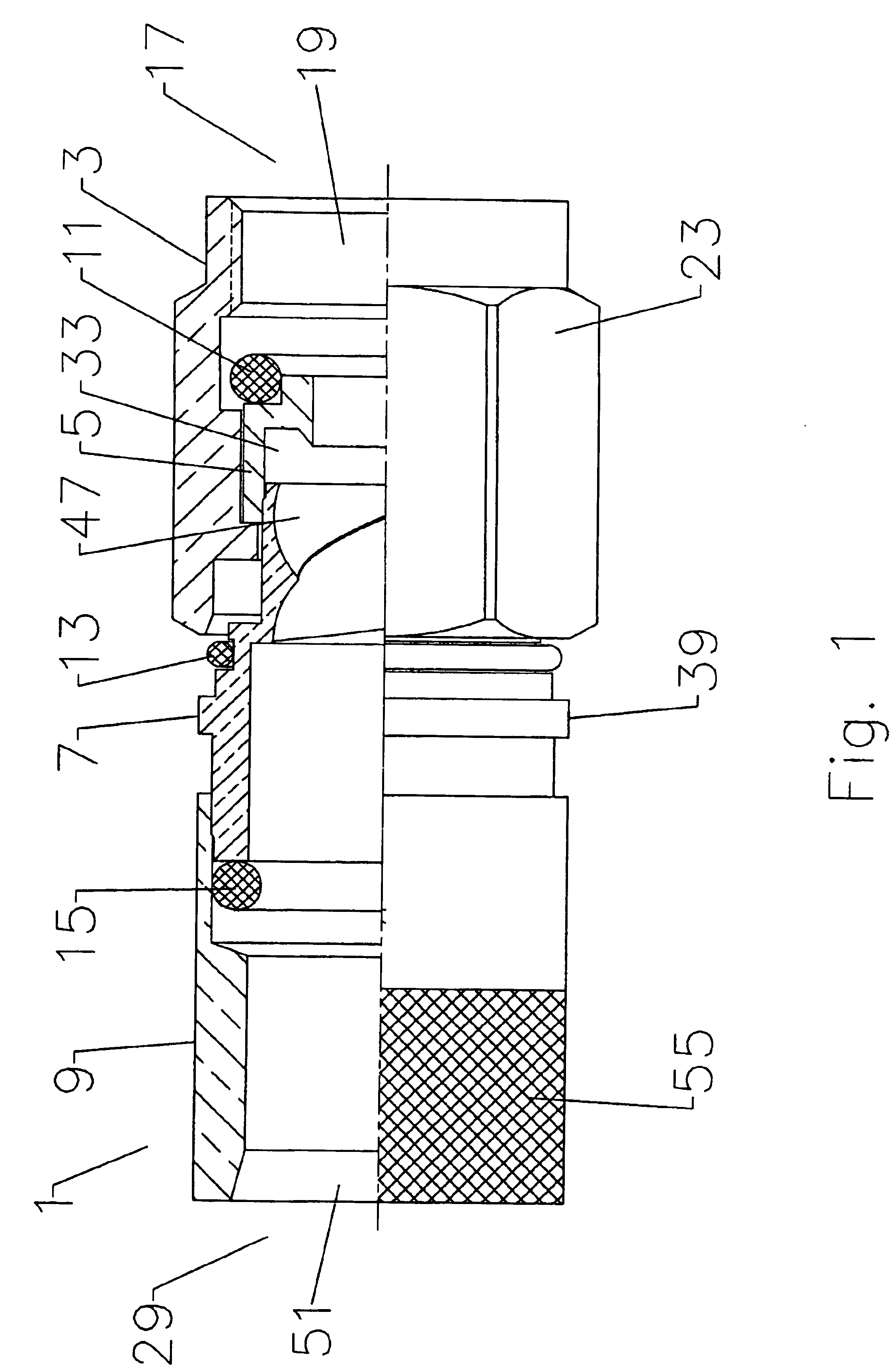
[0027]The invention will be described in detail with respect to FIGS. 1-6 in a standard Type-F (CATV) connector interface for use with 75 ohm helically corrugated outer conductor coaxial cable. One skilled in the art will appreciate that the invention, as will be discussed herein below, is similarly applicable to other connector interfaces and or helically corrugated coaxial cable configurations.

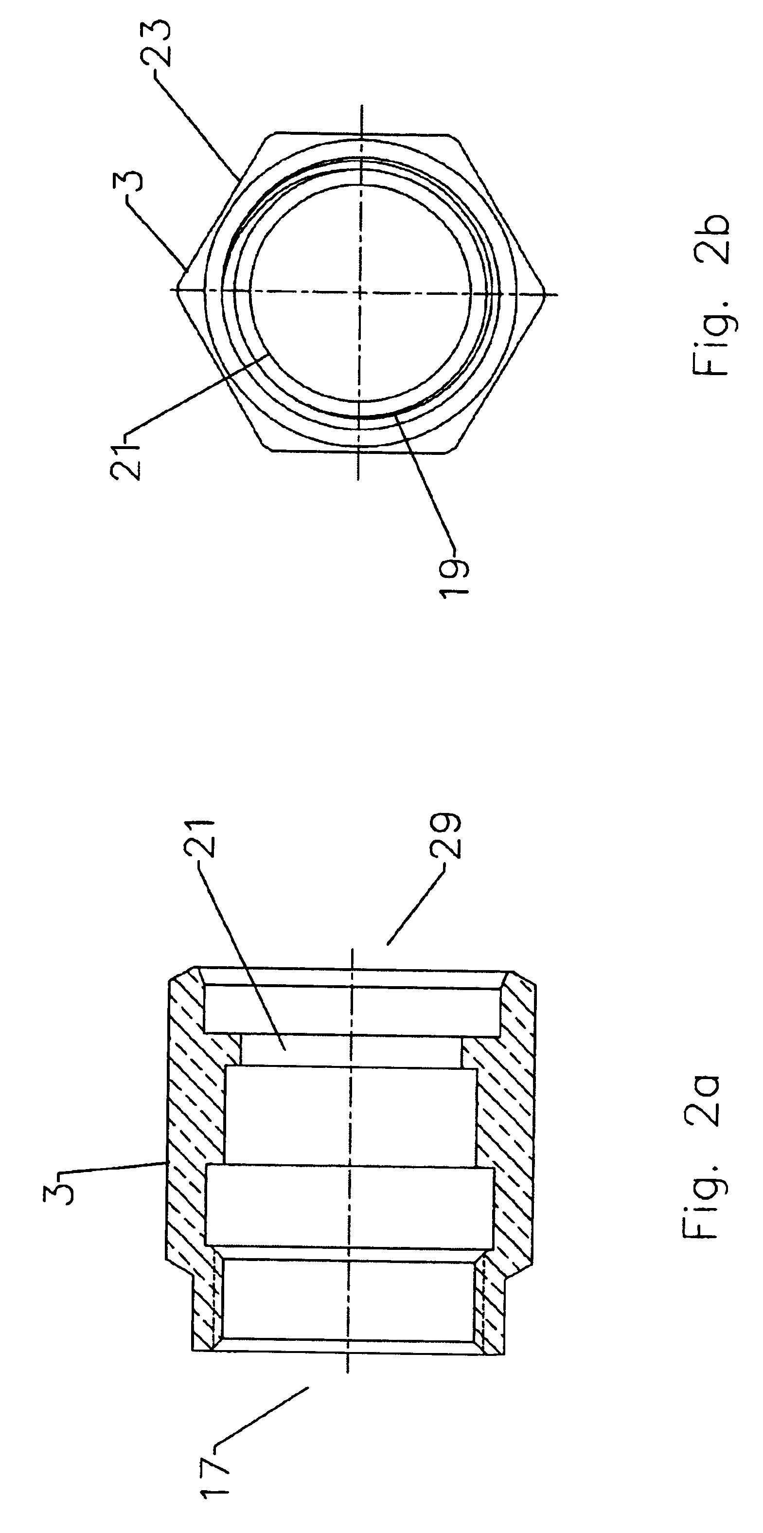
[0028]As shown in FIG. 1, a connector 1 comprises a coupling nut 3 surrounding an interface 5 which mates to a body 7 that fits into a sleeve 9. A plurality of compressible and or deformable sealing gaskets, for example rubber or silicon o-rings, may be located around and within the connector 1 to environmentally seal the connection(s). A first gasket 11 is located between the coupling nut 3 and the interface 5, seated upon the interface 5, to seal an interconnection between the connector 1 and a female connector. A second gasket 13 is located between the coupling nut 3 and the body 7, seate...


PUM


Abstract

An electrical connector adapted for interconnection with a helically corrugated outer conductor coaxial cable via axial compression. Threads formed in an interior bore of the connector body threadably engage helical corrugations of the outer conductor. Upon axial compression of an interface into an interference fit with the body, a leading edge of the outer conductor is deformed, creating a high quality uniform electrical interconnection and preventing unthreading of the cable from the connector. Gaskets environmentally sealing the various entry paths into the connector are also sealably compressed by the axial movement of the various connector components during axial compression.

Description

CROSS REFERENCE TO RELATED APPLICATIONS[0001]This application claims the benefit of U.S. Provisional Application No. 60 / 481,152 filed Jul. 28, 2003.BACKGROUND OF INVENTION[0002]1. Field of the Invention[0003]The invention relates to an electrical connector. More particularly the invention relates to an electrical connector installable upon an electrical cable, having a helically corrugated outer conductor, by application of axial compression.[0004]2. Description of Related Art[0005]Connectors for corrugated outer conductor cable are used throughout the semi-flexible corrugated coaxial cable industry.[0006]Previously, connectors have been designed to attach to coaxial cable using solder, crimping and or mechanical compression applied tangentially to the longitudinal axis of the cable. The quality of a solder connection may vary with the training and motivation of the installation personnel. Solder connections are time consuming and require specialized tools, especially during connect...

Claims


Application Information

Patent Timeline
Patent Type & Authority Patents(United States)
IPC IPC(8): H01R13/00H01R13/646H01R9/05H01R13/52
CPCH01R9/0521H01R24/564H01R13/5205H01R2103/00
Inventor ISLAM, NAHIDLEE, JOONTHORBURN, NEIL
Owner ANDREW LLC
Why Eureka
Try Eureka