
Removable small form factor fiber optic transceiver module and electromagnetic radiation shield

a technology of fiber optic transceiver module and electromagnetic radiation shield, which is applied in the direction of electrical apparatus construction details, coupling device connections, instruments, etc., to achieve the effect of limiting the speed (i.e., bandwidth) of the associated electrical device and small apertur

Inactive Publication Date: 2002-01-01
LUMENTUM OPERATIONS LLC
View PDF4 Cites 189 Cited by
  • Summary
  • Abstract
  • Description
  • Claims
  • Application Information

AI Technical Summary

Benefits of technology

Once assembled, the chassis then is substantially enclosed with shielding to suppress the escape of electromagnetic radiation. The shield is fabricated of electrically conducting sheet metal, such as thin metal plate stock, and formed into a channel shape. The channel shaped shield is provided with edge tabs. Each edge tab may be bent to form spring contacts which contact and electrically ground to a bracket or frame member; additionally, tabs may be bent over walls of the chassis to retain the shielding in its desired position. A separate shielding member is positionable on the chassis and retainable by bending or crimping of the edge tabs as contact between the separate shield and the edge tabs establishes grounding electrical contact therebetween. The emissions of electromagnetic radiation from the duplex port end of the chassis are reduced and modified by extending a shield member between the transmitter optical subassembly / receiver optical subassembly, bridging the separate shield and the channel shaped shield to reduce the size of the effective opening to attenuate the electromagnetic radiation passing through the duplex port end of the chassis.

Problems solved by technology

The operation of the electronics causes radiation of electromagnetic energy which may cause interference, if not suppressed, with nearby electromagnetic radiation sensitive equipment and components.

Method used


Image

  • Removable small form factor fiber optic transceiver module and electromagnetic radiation shield
  • Removable small form factor fiber optic transceiver module and electromagnetic radiation shield
  • Removable small form factor fiber optic transceiver module and electromagnetic radiation shield

Examples


Embodiment Construction

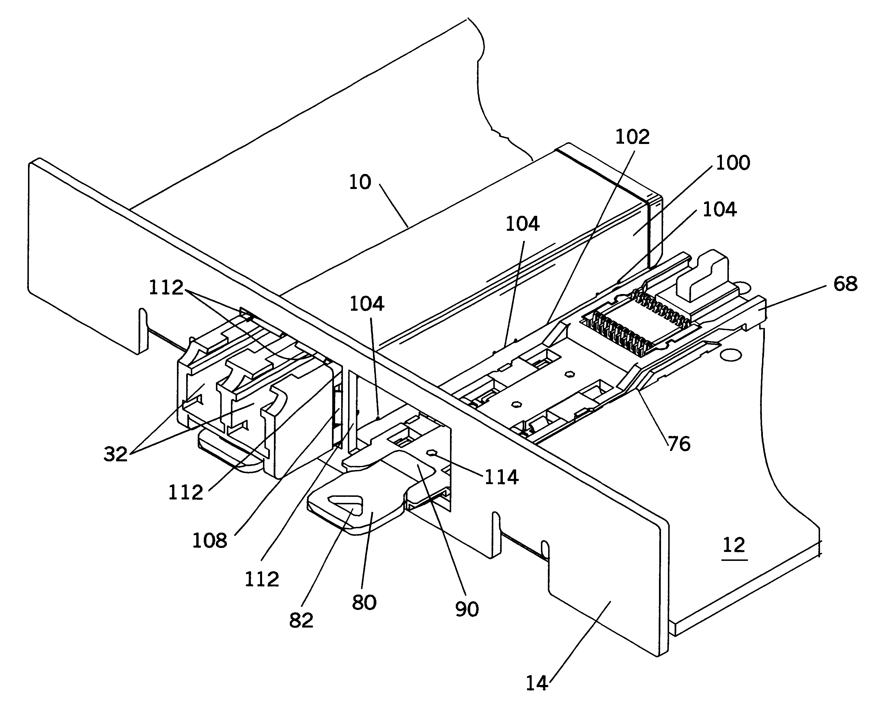
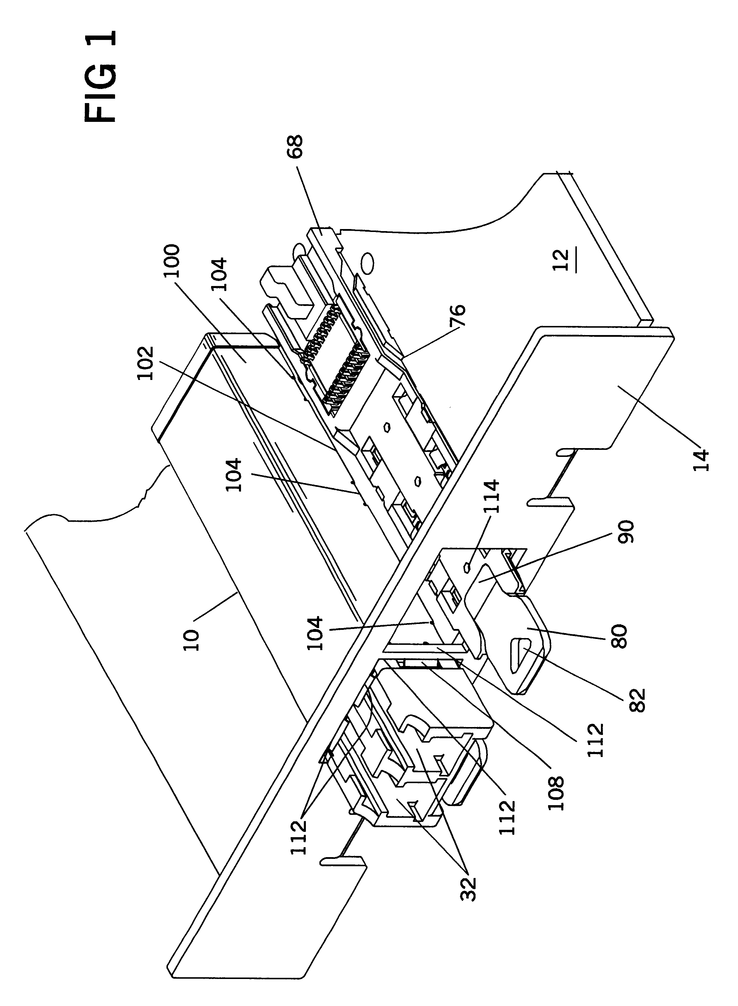
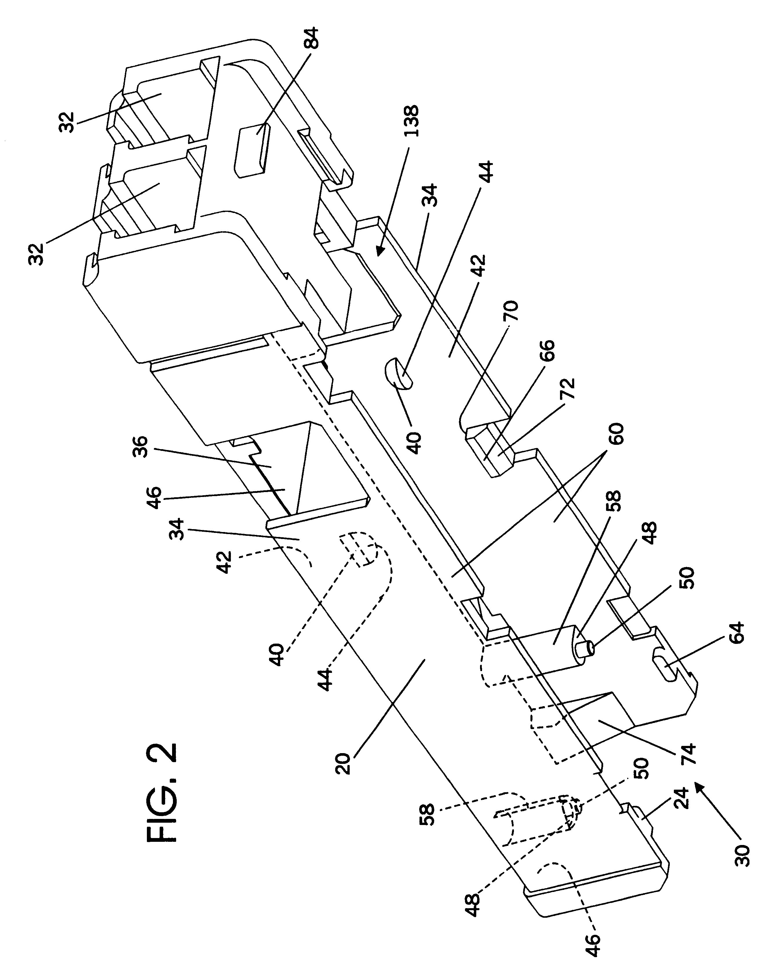
An insertable and removable electronic module is illustrated in the various figures of the drawings. The preferred type module is a duplex transceiver module incorporating a transmission optical subassembly and a receiver optical subassembly, also sometimes referred to as TOSA and ROSA, respectively.

Computers and particularly those computers which act as and are used as servers and controllers for networks are connected to communication lines which, in turn, are typically connected to other devices such as modems or other computers either directly or through other network connection lines.

Many connections between peripheral computers and servers are now being made through the use of fiber optic cable. Fiber optics present completely different requirements for interconnection to the electronic circuits and the previously widely used copper wire cable connections. The optical fiber must connect or interface with a light actuated diode or a light emitting diode which convert some incom...


PUM


Abstract

An easily removable modular optical signal transceiver unit for conversion between modulated light signal transmission and electronic data signals and which conforms to the Small Form Factor standard for transceiver interfaces is disclosed. The structural details of its chassis include aspects which insure the proper positioning of electronic circuit boards of a transmitter optical subassembly and a receiver optical subassembly as well as the positioning of electromagnetic radiation shielding on the chassis. In conjunction with an interface device on an electronic circuit board of a host device, the chassis supports electromagnetic radiation shielding which substantially encloses the sources of electromagnetic radiation within the module and suppresses the escape of electromagnetic radiation, thereby preventing electromagnetic interference with sensitive components and devices in proximity to the module.

Description

THE FIELD OF THE INVENTIONThis invention relates to the simple fabrication of removable electronic interface modules for connecting fiber optic communication or signal lines to a computer and, more specifically, to the shielding that forms a part of the module for collecting and suppressing the electromagnetic radiation generated and radiated by electronic components of the module.Computers increasingly are being connected to communications lines and other devices or networks with the computers performing as servers to the peripherally connected computers or devices. The volume of data sent and received by the computer serving as a server of a network is such that the networks are advantageously constructed using fiber optic lines in order to increase the throughput of data.Fiber optic lines and the associated fiber optic signals require transceivers to convert the optical light pulse signals to electronic signals which are usable by the computer. Such a transceiver includes a trans...

Claims


Application Information

Patent Timeline
IPC IPC(8): G02B6/42H05K9/00
CPCG02B6/4201H05K9/0058G02B6/4292G02B6/4277G02B6/4246G02B6/4261G02B6/4284
Inventor BRANCH, SCOTT M.GAIO, DAVID PETERHOGAN, WILLIAM K.
Owner LUMENTUM OPERATIONS LLC
Learn More