
Prosthetic liner

a technology of prosthetic lines and silicone, applied in the field of prosthetic lines, can solve the problems of not providing substantial resistance to silicone distension, the weight of the suction liner,

Inactive Publication Date: 2004-07-15
KAUPTHING BANK
View PDF11 Cites 60 Cited by
  • Summary
  • Abstract
  • Description
  • Claims
  • Application Information

AI Technical Summary

Problems solved by technology

It has been observed, however, that as the thickness of the silicone elastomer cushion grows, so does the weight of the suction liner.
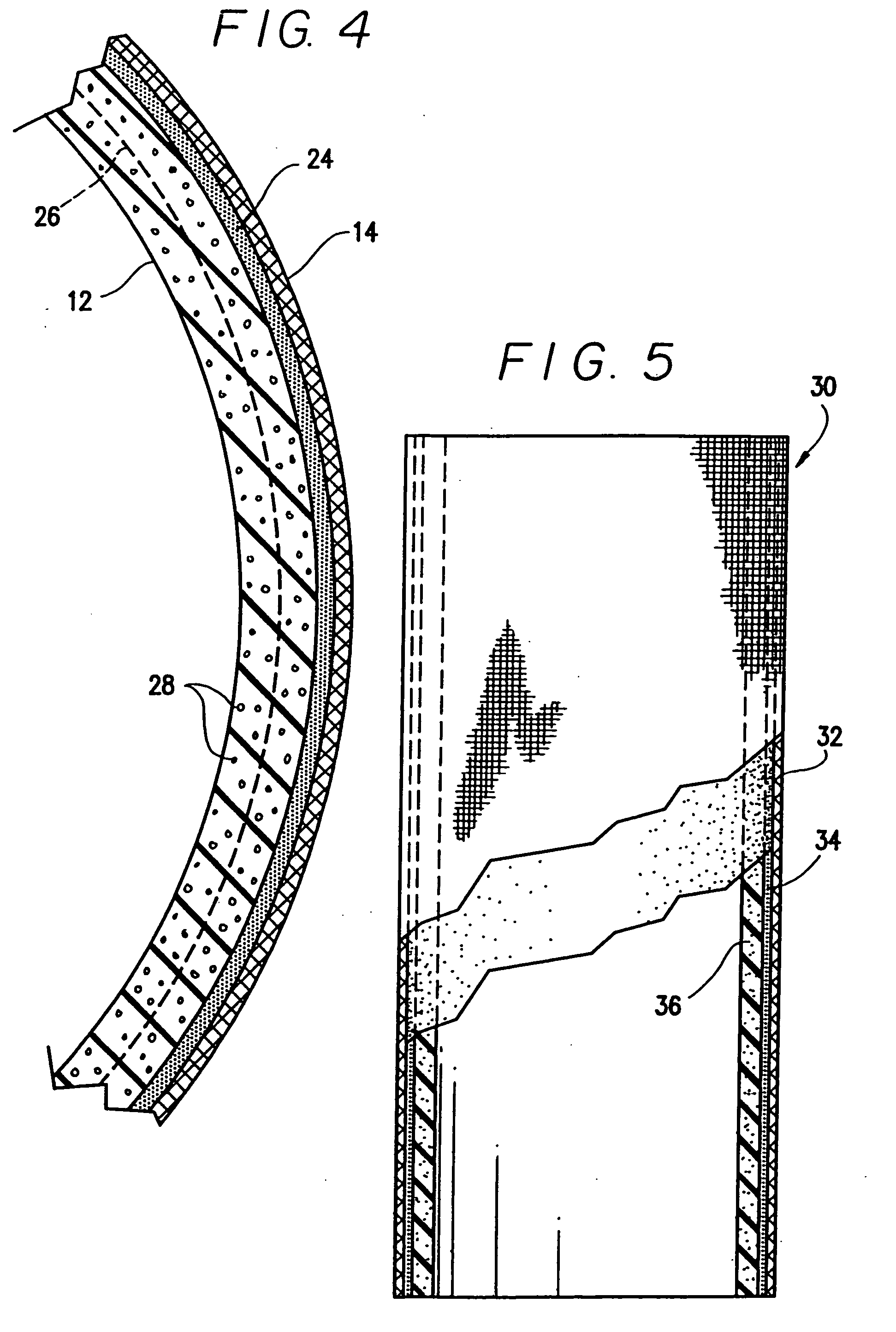
When used in a suction liner, the composite elastic material may include a distension controlling reinforcement matrix embedded in the silicone elastomer layer over a distal end area of the suction liner, wherein the reinforcement matrix, for example a circular knit textile, contains reinforcement elements that provide substantial stiffness against elongation of the liner in a direction along the liner length but which do not provide substantial resistance against distension of the silicone elastomer layer in directions transverse to the liner length.

Method used


Image

  • Prosthetic liner
  • Prosthetic liner
  • Prosthetic liner

Examples


Embodiment Construction

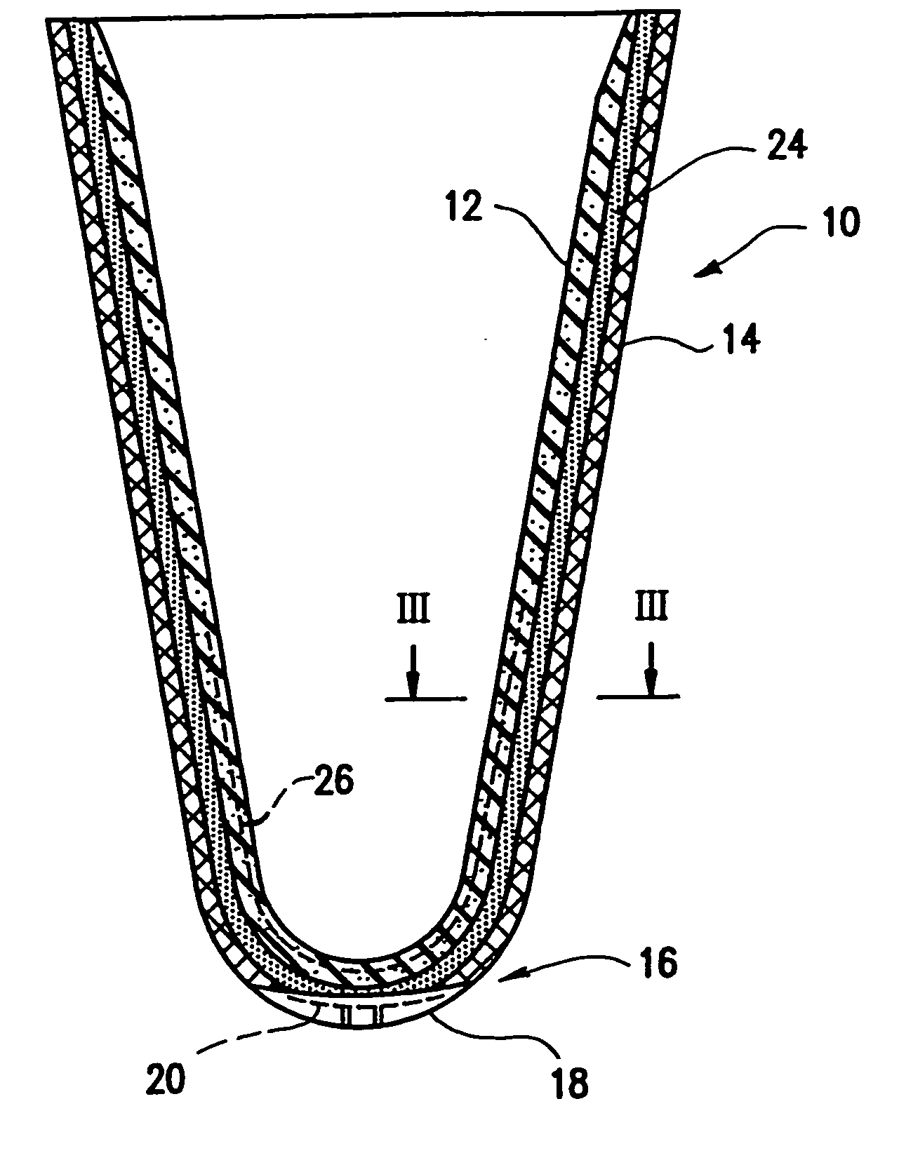
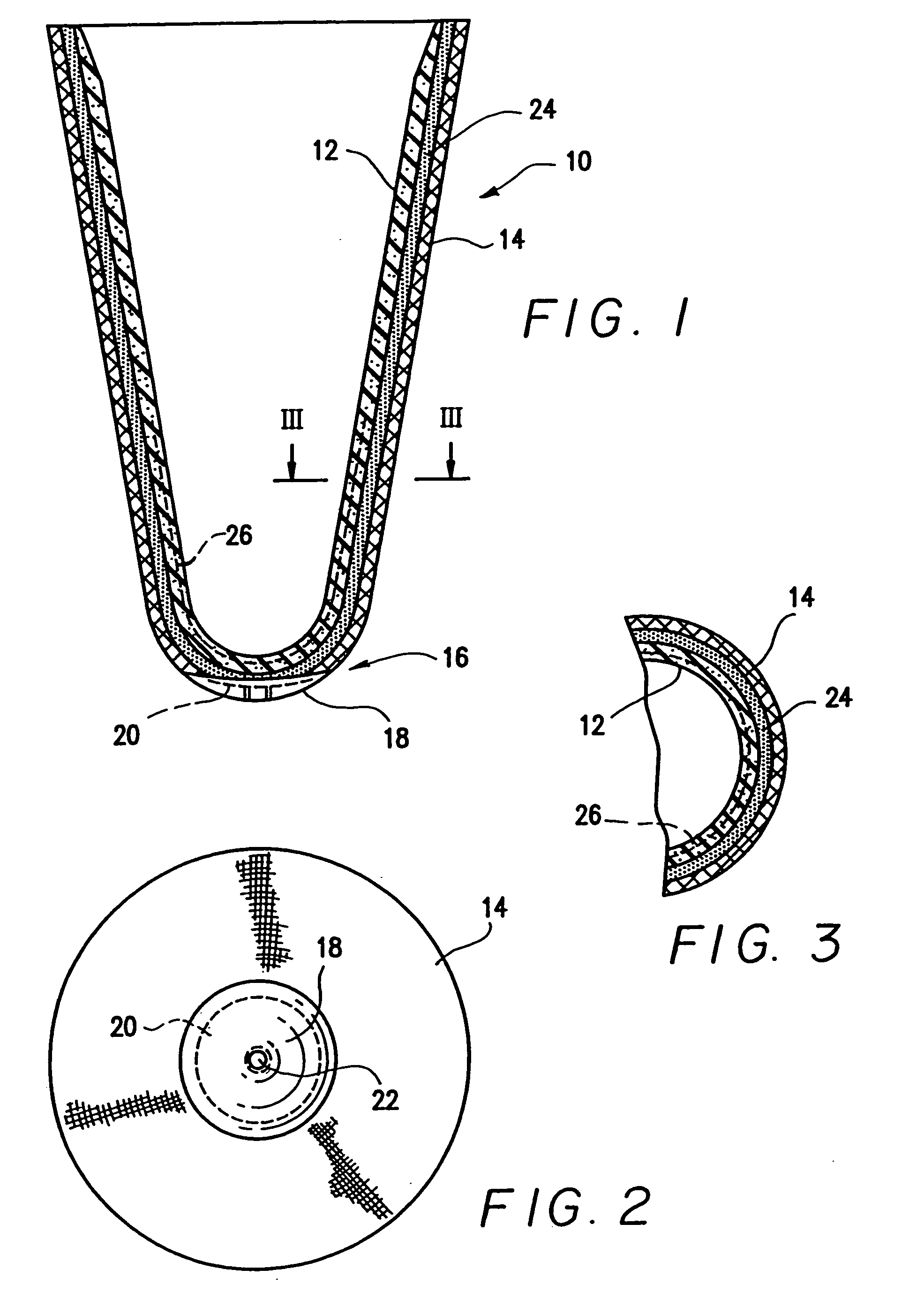
[0034] FIG. 1 schematically illustrates in a cross-section view a prosthetic suction liner 10 formed in part of a composite elastic material 12 on its interior surface and an elasticized fabric layer 14 on its exterior surface at least up to its distal end area 16, where a distal end cap 18 having embedded therein a rigid prosthetic connector 20 formed, for example, of aluminum or other metal, or rigid plastic such as Nylon.

[0035] The liner 10 is formed as a close ended tapered tubular element, as is conventional for such suction liners. The distal end cap 18 firmly joins the prosthetic connector 20 to the suction liner 10 while providing a cushioning and stabilizing surface at the distal end of the liner. The prosthetic connector 20 includes preferably a threaded aperture 22 for providing access to a threaded prosthetic pin connector in a manner well known in the art.

[0036] FIG. 2 shows the suction liner in an end view as seen from the distal end of the liner.

[0037] FIG. 3 is a cro...


PUM

PropertyMeasurementUnit
Lengthaaaaaaaaaa
Thicknessaaaaaaaaaa
Radiusaaaaaaaaaa

Abstract

Prosthetic liner formed of a molded silicone elastomer material including an inner wall, a circular outer wall having radii of curvature centered along a first longitudinal axis of external symmetry extending longitudinally centrally within the liner, the inner wall including a circular curved inside anterior wall portion extending along a liner length and having first radii of curvature centered on a second longitudinal axis of anterior curvature extending longitudinally along the liner length and a circular curved inside posterior wall portion having a second radii of curvature centered on a third longitudinal axis of posterior curvature extending along said liner length. The first, second and third longitudinal axes lie in a common longitudinally and transversely extending plane bisecting the anterior and posterior wall portions, and the second and third axes are spaced apart a predetermined offset distance on opposed sides of the first axis to thereby define an anterior wall portion that is thicker along the liner length than the posterior portion.

Description

[0001] This application is a divisional application of U.S. patent application Ser. No. 09 / 805,125 filed on Mar. 14, 2001, which claims the benefit of Provisional Application No. 60 / 189,039 filed Mar. 14, 2000.1. FIELD OF THE INVENTION[0002] This invention relates to liners useful for prosthetic applications.2. BACKGROUND OF THE INVENTION[0003] Various silicone elastomer materials have been proposed for use in prosthetic devices such as suction liners of the type described in U.S. Pat. No. 4,923,474 granted to Klasson and Kristinsson on May 8, 1990. Other examples of such suction liners include U.S. Pat. No. 5,728,168 granted Mar. 17, 1998 to Laghi et al. and U.S. Pat. No. 5,830,237 granted to Kania Nov. 3, 1998.[0004] Composite elastomer materials useful for both suction liners and sealing sleeves are disclosed in U.S. Pat. No. 5,571,208 granted Nov. 5, 1996 to Caspers.[0005] It is highly desirable to provide a relatively soft cushion in contact with or adjacent the skin of the use...

Claims


Application Information

Patent Timeline
IPC IPC(8): A61F2/80A61F2/00A61F2/50A61F2/78A61F13/00A61L15/22A61L27/18A61L27/44B23B27/04B23B27/12B29C35/02B29C43/18B29C49/02B29C70/44B29C70/46B29D23/00
CPCA61F2/5046Y10T428/1352A61F2/80A61F2002/3007A61F2002/802A61F2240/001B29C35/02B29C49/02B29C70/44B29C70/467B29D23/001B29K2083/005B29K2105/04B29K2105/0809B29K2105/0854B29K2105/246B29L2009/00B29L2023/007B29L2031/7532B29D23/00A61F2002/5055A61F2002/7818B32B5/02B32B25/10B32B25/20B32B2262/0261B32B2307/51B32B2535/00Y10T428/1372Y10T428/1314Y10T428/24388Y10T428/1362Y10T428/13A61F2/7812B32B2264/00Y10T442/3016Y10T442/40Y10T442/20Y10T442/413Y10T442/3008A61L27/40
Inventor JANUSSON, HILMARTHORSTEINSSON, FREYGAROURASGEIRSSON, SIGUROUR A.EINARSSON, PALMI
Owner KAUPTHING BANK
Learn More