
Elevator car position determining system and method using a signal filling technique

a signal filling and elevator car technology, applied in the direction of elevators, instruments, using mechanical means, etc., can solve the problems of increasing the installed cost, pvt-based approximation system may have errors, and it is difficult to blend pvt-based position feedback with the vane-based position feedback,

Inactive Publication Date: 2009-10-06
OTIS ELEVATOR CO
View PDF12 Cites 38 Cited by
  • Summary
  • Abstract
  • Description
  • Claims
  • Application Information

AI Technical Summary

Benefits of technology

The present invention provides an improved elevator car position determining system and method. The system includes a leading sensor and a lagging sensor mounted on the elevator car, with the leading sensor being spaced from the lagging sensor by an offset distance. The system also includes multiple spaced apart position indicators along the pathway of the elevator car. The signals from the sensors are received and used to determine the position of the elevator car by using a correction factor established from the position sensed by the other sensor and the offset distance. This system helps to accurately determine the position of the elevator car in the elevator shaft.

Problems solved by technology

Determining car position in express zones presents a particular challenge since a PVT-based approximation system may have errors due to rope stretch, slip, etc.
The car position may be corrected upon detection of a door zone vane at the end of the express zone; however, the longer the express zone the more difficult it is to blend in the PVT-based position feedback with the vane-based position feedback.
In order to provide a smoother transition, additional vanes have been mounted in the express zone, thus increasing the installed cost.
The main disadvantage of current systems is the relatively high installed cost resulting from the multitude of sensors and vanes, mounted on different tracks (for NTSD, ETSD and door zones) and an additional channel on machine speed encoder.

Method used


Image

  • Elevator car position determining system and method using a signal filling technique
  • Elevator car position determining system and method using a signal filling technique
  • Elevator car position determining system and method using a signal filling technique

Examples


Embodiment Construction

)

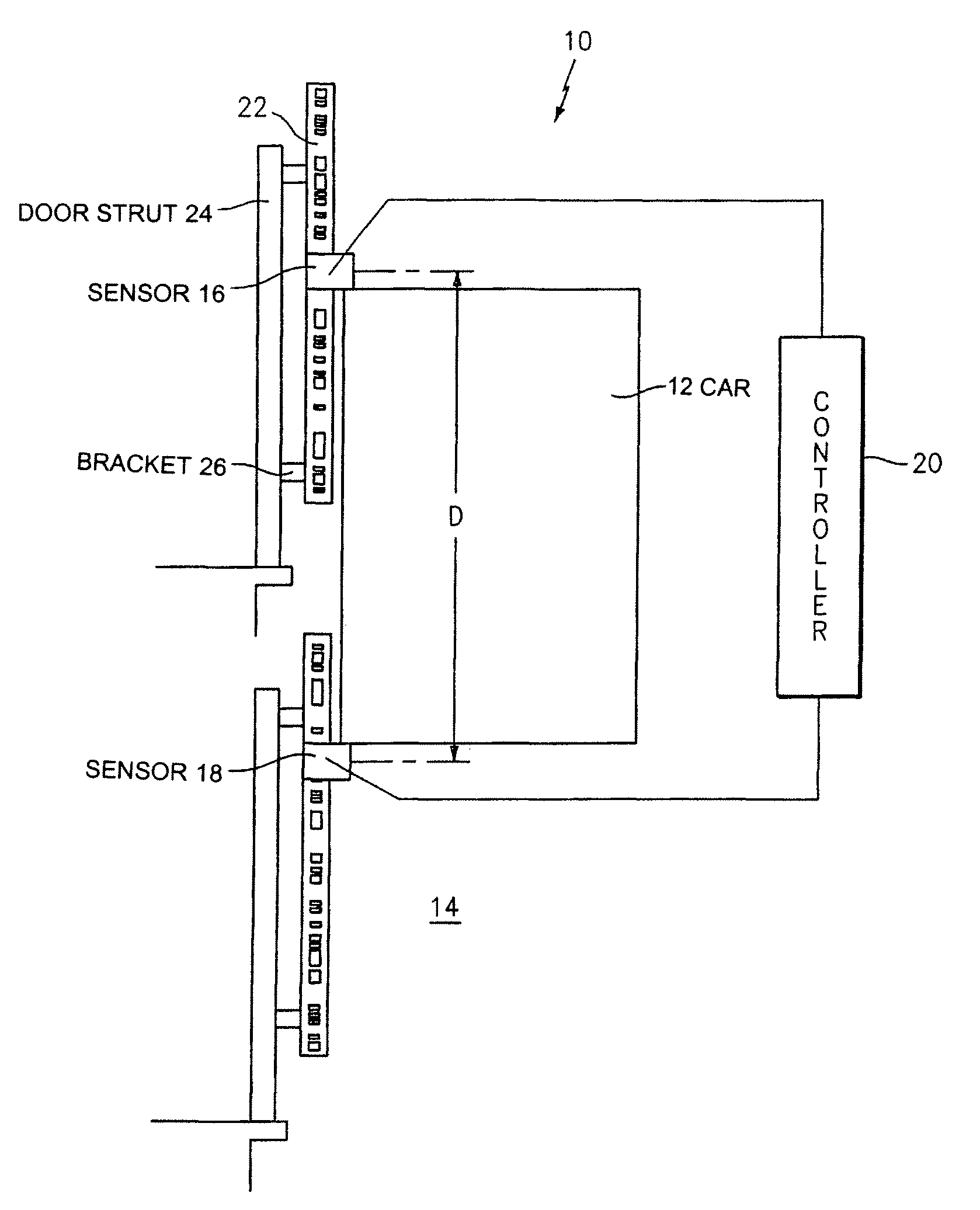
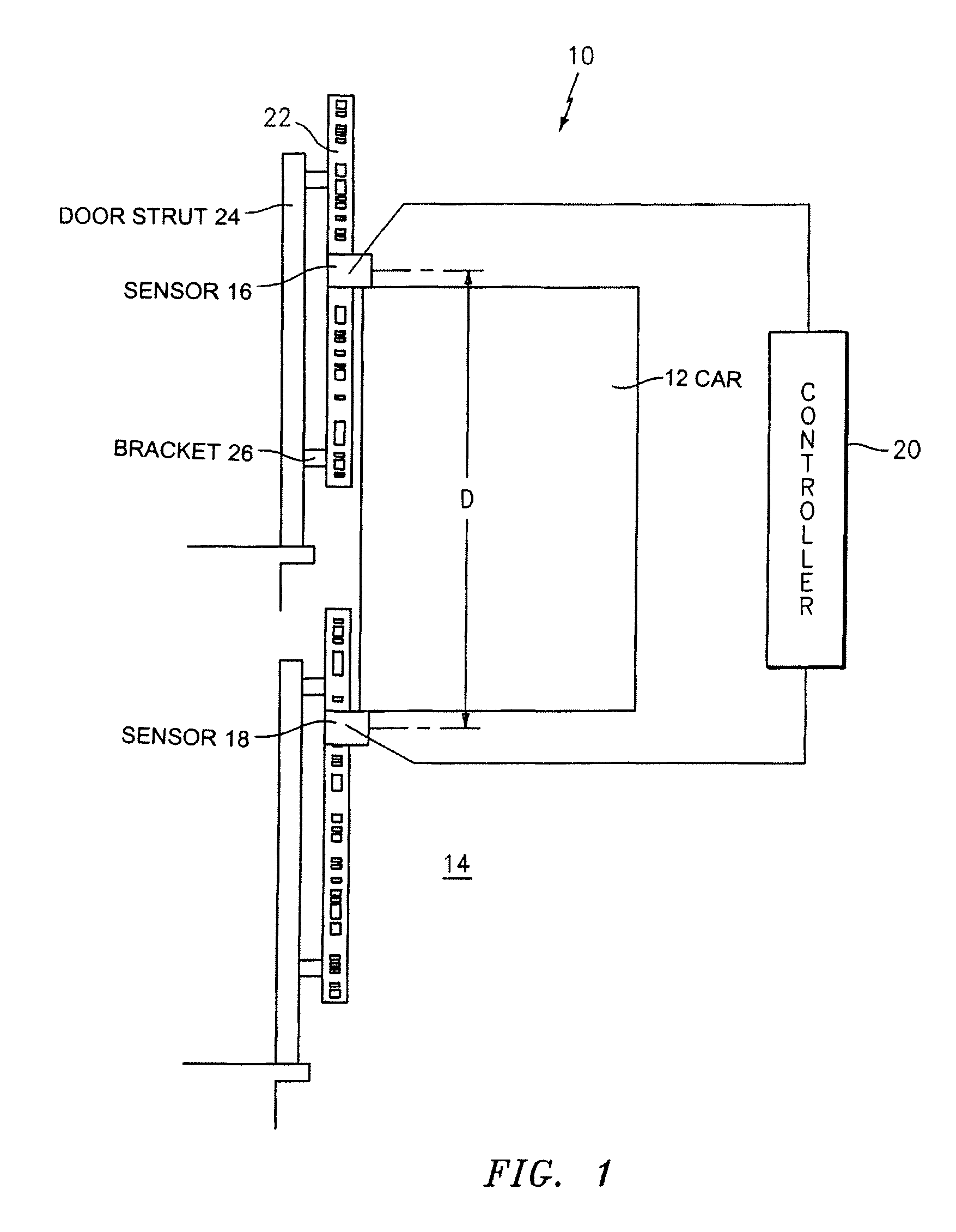
[0019]Referring now to the drawings, FIG. 1 illustrates an elevator car position determining system 10. The system 10 includes an elevator car 12 which moves in an elevator hoistway 14. The car 12 has a first sensor 16 mounted on top of the car and a second sensor 18 mounted at the bottom of the car. The sensors 16 and 18 are offset from each other by a distance D. Depending on the movement of the car 12, one of the sensors 16 and 18 will be the leading sensor (the first sensor in the direction of movement) and the other will be the lagging sensor (the second sensor in the direction of movement). While the sensors 16 and 18 have been described as being mounted to the top and the bottom of the car, they could be located in other positions if desired, provided that they are aligned and offset from each other.

[0020]Each of the sensors 16 and 18 communicates with a controller 20. The controller 20 may be any suitable processor known in the art.

[0021]The system 10 also includes a plural...


PUM


Abstract

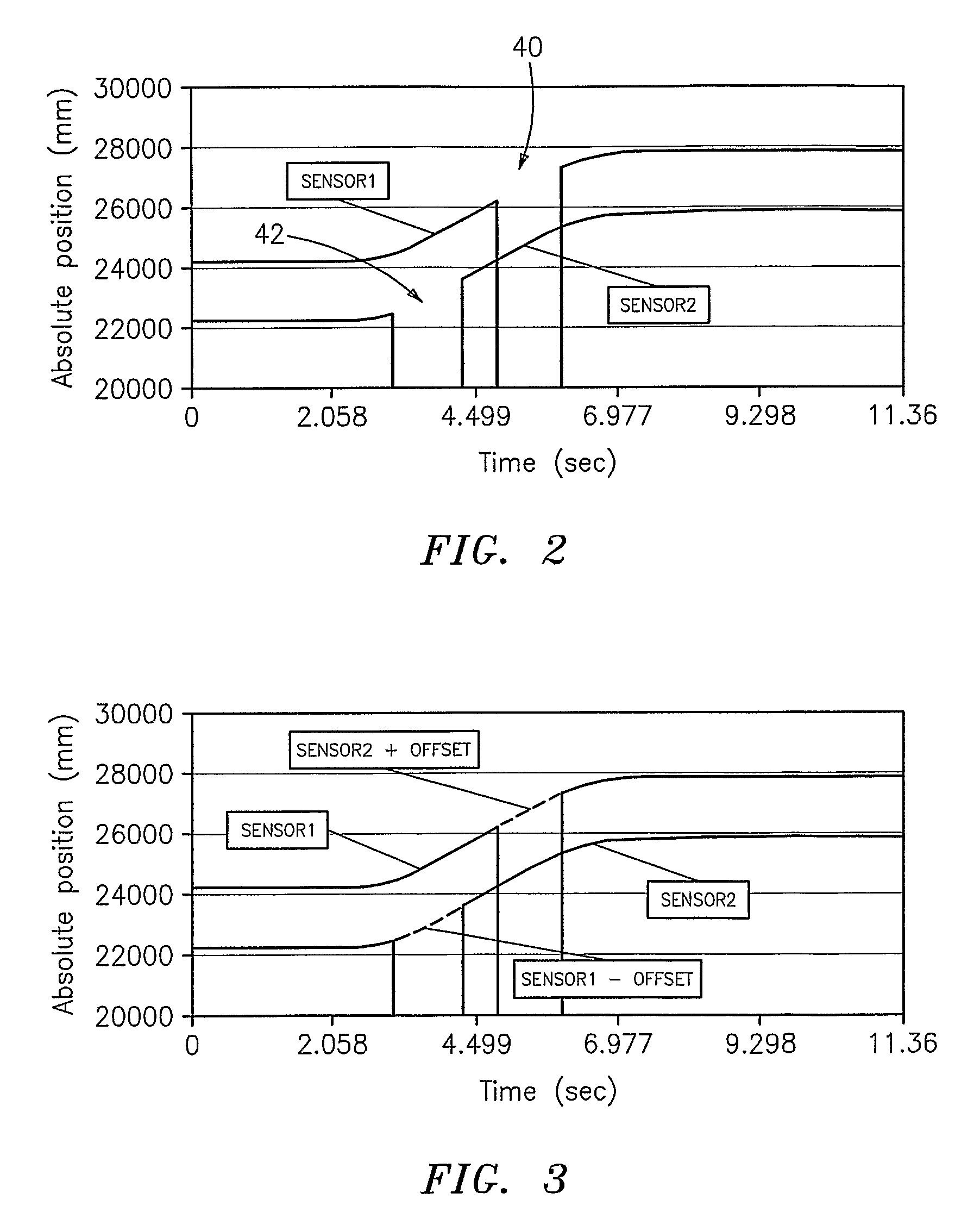
A method for determining a position of a moving object, such as an elevator car in an elevator shaft, includes the steps of mounting a leading sensor and a lagging sensor to the moving object and spacing the leading sensor from the lagging sensor by an offset distance, mounting a plurality of spaced apart position indicators along a pathway of the moving object, transmitting signals representative of object position from the leading sensor and the lagging sensor to a controller as the sensors pass the spaced apart position indicators, and filling any gaps in the signal gathered from one of the sensors by using a correction factor established from the position sensed by the other sensor and the offset distance. A system for performing the method is described.

Description

BACKGROUND OF THE INVENTION[0001](1) Field of the Invention[0002]The present invention relates to a system and a method for determining the position of a moving object and more specifically to a system and a method for determining the position of an elevator car.[0003](2) Prior Art[0004]A technique, known as the PVT position approximation technique, has been widely used in industry to determine the position of elevator cars. The PVT technique uses machine encoder information, also known as the primary velocity transducer or PVT, corrected to vanes mounted at fixed locations in the hoistway. Determining car position in express zones presents a particular challenge since a PVT-based approximation system may have errors due to rope stretch, slip, etc. The car position may be corrected upon detection of a door zone vane at the end of the express zone; however, the longer the express zone the more difficult it is to blend in the PVT-based position feedback with the vane-based position fe...

Claims


Application Information

Patent Timeline
Patent Type & Authority Patents(United States)
IPC IPC(8): B66B3/02
CPCB66B1/3492
Inventor ZAHARIA, VLAD
Owner OTIS ELEVATOR CO
Learn More