3D display system using a lenticular lens array variably spaced apart from a display screen

a technology of lenticular lens array and display screen, which is applied in the field of three-dimensional (3d) image display system, can solve the problems of lenticular sheet, varies among differing offset distances, and is not suitable for display technology used in computers, handheld electronic and computer devices,

Inactive Publication Date: 2009-09-10
GENIE LENS TECH
View PDF46 Cites 39 Cited by
  • Summary
  • Abstract
  • Description
  • Claims
  • Application Information

AI Technical Summary

Benefits of technology

[0010]Embodiments of the display system of the present invention address these problems by providing a lens assembly that includes a lens array or lens substrate with a plurality of elongate, parallel lenses or lenticules that are configured to focus through the substrate or array to a location (e.g., a focal plane or region) that is spaced apart from the back surface the lens substrate or array. This configuration of the lens array allows the lens assembly to focus into the display screen (e.g., through the outer glass / plastic layer or further) and, preferably, on or near the inner display surface or region. In some embodiments, the lens array is placed directly on an outer surface of the display screen adjacent the portion of the screen displaying the electronic or digital image. Such embodiments may involve determining the offset distance or location of the inner display surface or region relative to the outer surface of the display screen for each display screen, and then manufacturing a lens array adapted for use with each of these display screens (e.g., a set of lens arrays or substrates with differing lenticules or lens configurations selected to suit the particular display screen and / or display technology such as a CRT screen versus a LCD screen or the like).

Problems solved by technology

Conventional lenticular sheets are, as a result, not suited for use with the display technology used for computers, handheld electronic and computer devices, DVD players, televisions, and other electronics because these devices do not display the image on their outer surfaces.
Another problem with attempting to display electronic or digital interlaced images using existing display technology is that the offset distance varies among differing electronic devices and even among differing manufacturers of a similar device.
As a result, a lens array that may be suited for one device may not be useful with another device as the range of offsets is generally about 1 / 32 to about 3 inches or more.

Method used


Image

  • 3D display system using a lenticular lens array variably spaced apart from a display screen
  • 3D display system using a lenticular lens array variably spaced apart from a display screen
  • 3D display system using a lenticular lens array variably spaced apart from a display screen

Examples


Embodiment Construction

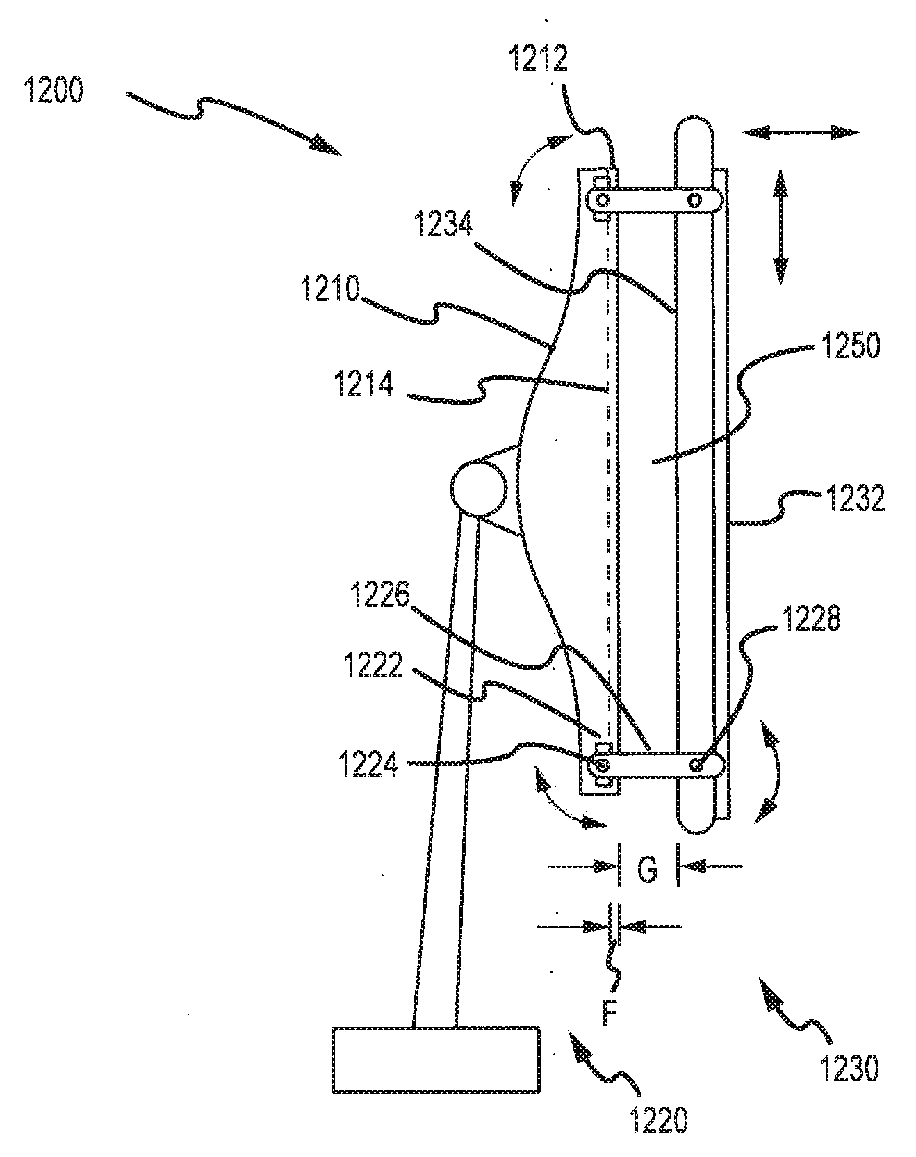
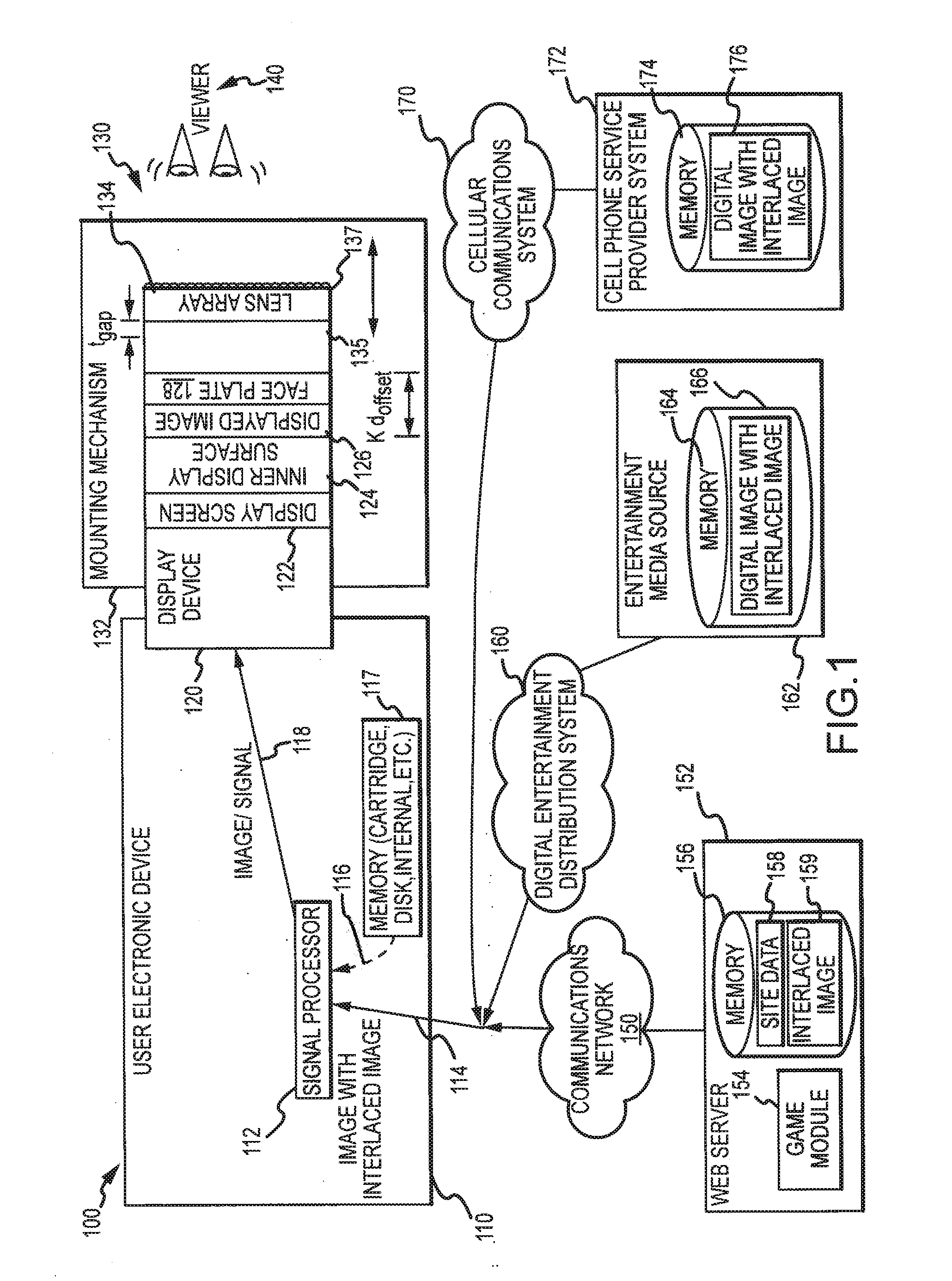
[0027]Generally, the present invention is directed to an image display system and image display methods that utilize a lens assembly with a lens array that is iniquely suited for use with interlaced images displayed using electronic display devices such as computer monitor and other computer screens, handheld electronic device screens, DVD and other videos player device screens, and television and similar display screens. In the display systems described herein, these display devices are used to display an interlaced image, e.g., a still or video image with 3D or other special effects, such as may be displayed from memory, a DVD or other removable memory device or media, or from a transmitted signal such as a transmission of digital data from a web server over the Internet or a television or other entertainment broadcast (e.g., digital cable or satellite television signals, video or other games provided over the Internet, or the like). The display device typically includes a display...


PUM


Abstract

An image display system for displaying interlaced images to achieve three dimensional effects. The system includes a user electronic device, such as a computer or television, with a display with a faceplate. The electronic device operates the display to generate an image that includes an interlaced portion at an inner display surface or location at an internal offset distance from an outer surface of the faceplate. The image display system includes a lens array with lenticules configured to focus through the lens array material, through an air gap, and into the faceplate the internal offset distance rather than simply on the back of the lens array. The display system may also include a mounting mechanism for selectively positioning the lens array relative to the faceplate to adjust the size of the air gap so as to focus the lens array onto the image being displayed within the display device.

Description

BACKGROUND OF THE INVENTION[0001]1. Field of the Invention[0002]The present invention relates, in general, to methods and devices for displaying three dimensional (3D) images including lens arrays and devices for use in viewing or displaying images that are interlaced to display animated, 3D, and other images, and, more particularly, to display or optical systems, as well as products incorporating such systems and methods of using such systems, that include a lenticular lens array or substrate used in combination with electronic devices, such as computers and handheld electronic devices and televisions, to allow a user to clearly view or focus on an image displayed on the display screen or monitor of the electronic device (e.g., a digital image including a set of interlaced images).[0003]2. Relevant Background[0004]For many years, entities doing business on the internet have searched for ways to drive user traffic to their web sites. Many web sites have even been created with the so...

Claims


Application Information

Patent Timeline
Patent Type & Authority Applications(United States)
IPC IPC(8): H04N13/04
CPCH04N2213/001H04N13/0404H04N13/305
Inventor RAYMOND, MARK A.LANGE, HOWARD G.SEIFERT, WILLIAM K.
Owner GENIE LENS TECH
Why Eureka
Try Eureka