Orienting and feeding apparatus and method for manufacturing line

a technology of feeding apparatus and manufacturing line, which is applied in the direction of conveyors, conveyor parts, transportation and packaging, etc., can solve the problems of inability to quickly orient and feed elongated objects of the foregoing types, and the device is unfortunately not capable of rapid and accurate processing of objects

Inactive Publication Date: 2004-07-29
NORWALT DESIGN
View PDF5 Cites 46 Cited by
  • Summary
  • Abstract
  • Description
  • Claims
  • Application Information

AI Technical Summary

Benefits of technology

0006] Now in accordance with the present invention we have devised apparatus and methods which are fully capable of rapidly orienting and feeding generally cylindrical, substantially identical elongated objects which are broadly characterized by having a maximum transverse diameter Y. In accordance with the invention first and second continuous conveying belts are provided having input and output ends for cooperatively conveying such objects toward a downstream processing line. The belts are mounted so that their respective conveying surfaces are movable in a common parallel direction. The facing edges of the conveying surfaces of these belts are spaced from one another to define a uniform gap between them of a dimension less than Y. The conveying surfaces reside and are movable in planes which are upwardly sloped away from the gap. The surfaces thereby define a zone converging downwardly in the direction of the gap. Object...

Problems solved by technology

In the past it has proved very difficult to orient and feed elongated objects of the foregoing types i...

Method used


Image

  • Orienting and feeding apparatus and method for manufacturing line
  • Orienting and feeding apparatus and method for manufacturing line
  • Orienting and feeding apparatus and method for manufacturing line

Examples


Embodiment Construction

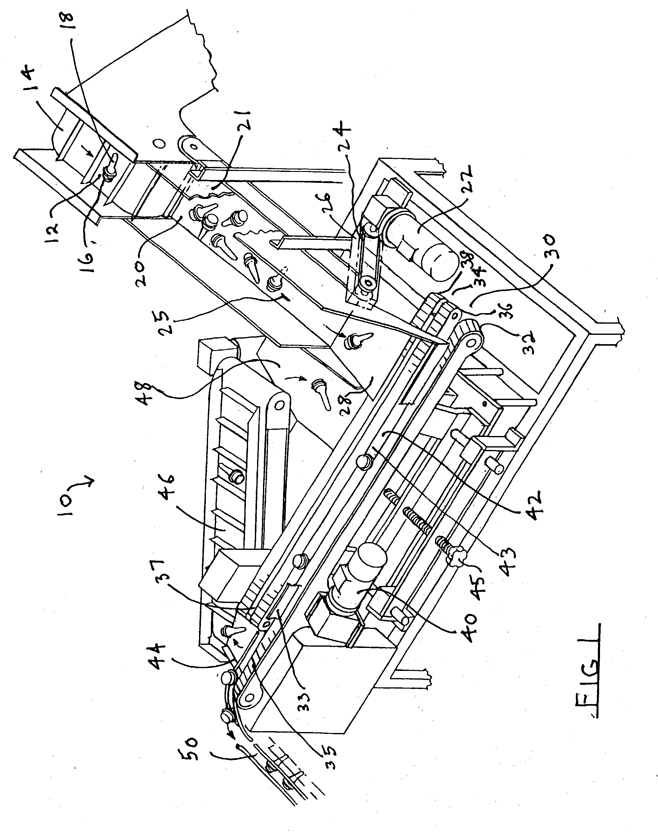
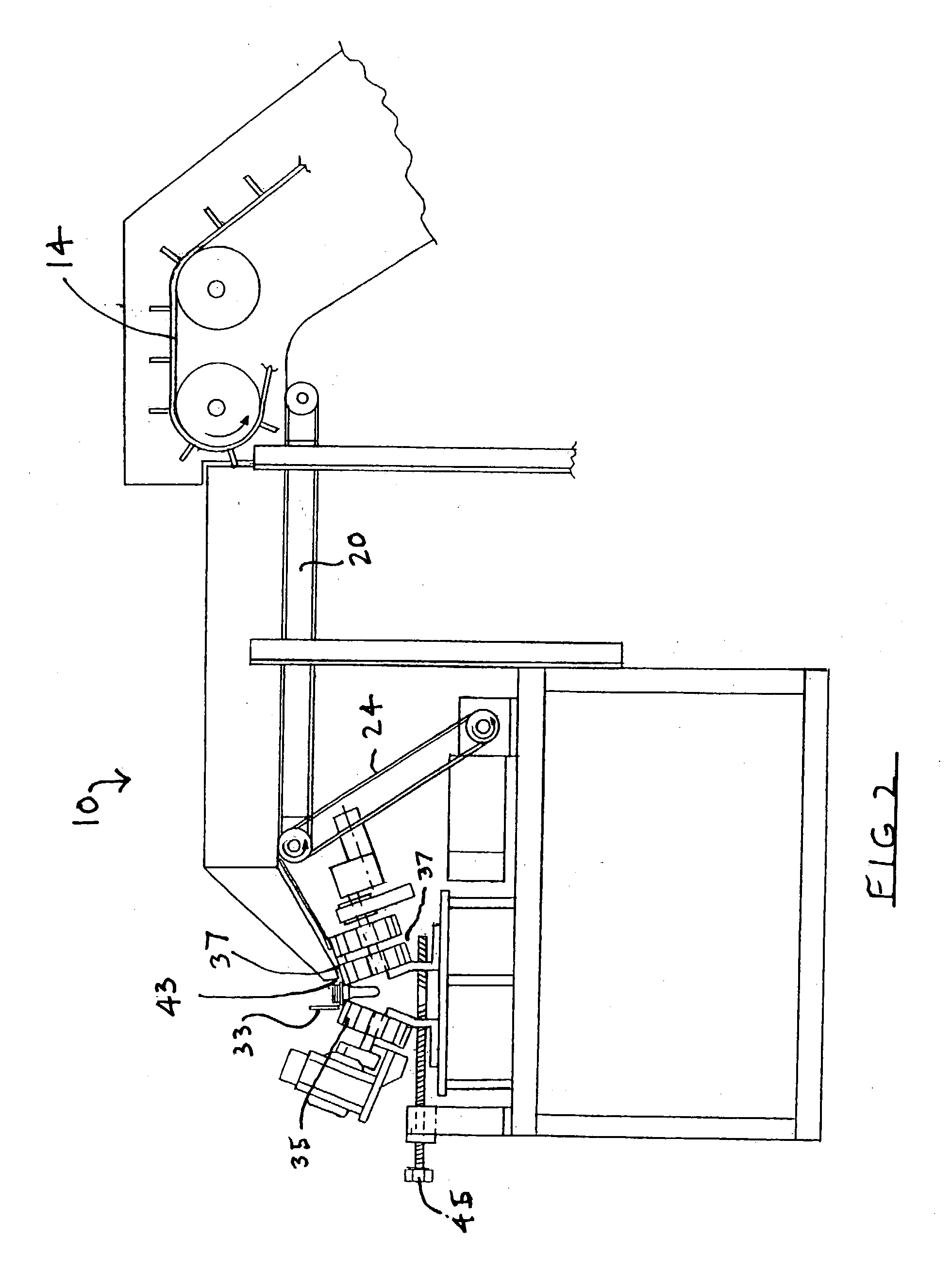
[0013] The apparatus 10 shown in FIGS. 1 and 2 is particularly useful for orienting and feeding preforms of a type that has been previously discussed. These preforms are intended for orienting and feeding to a downstream processing point where they will be subjected to a blow molding process in order to produce a container of the type commonly used for various liquids such as large plastic beverage containers and the like. These preforms 12 are fed from an input bin (not shown) via a supply input belt 14. The representative preform 12 is a moldable plastic product which is well known. It is a unitary structure having an enlarged threaded portion 16 from which extends a tubular portion 18 which is of reduced diameter and which is heavier than the portion 16. As has previously been discussed the threaded portion 16 will ultimately form the neck of the blow-molded container, whereas the tubular portion 18 will form the hollow body of the container. The preform 12 is seen to be generall...


PUM


Abstract

Apparatus and methods for rapidly orienting and feeding generally cylindrical, elongated objects having a maximum transverse diameter Y. First and second conveying belts are provided having input and output ends for cooperatively conveying such objects toward a downstream processing line. The belts are mounted so that their respective conveying surfaces are movable in a common parallel direction. The facing edges of the conveying surfaces of these belts are spaced from one another to define a uniform gap between them of a dimension less than Y. The conveying surfaces are upwardly sloped away from the gap, to define a zone converging downwardly in the direction of the gap. Object input means deposit the initially unoriented elongated objects at the input ends of the conveying belts. The belts are moved in a common direction, but at different speeds. The elongated objects are rotated by contact with the differentially speeding belts as they descend into the converging zone and become supported at the gap and conveyed by riding on the edges of the moving belts which border the gap. The objects as they descend become oriented in positions of gravitationally maximum stability relative to the mode of support, these positions being characteristic for the objects. Object output means at the ends of the belts receive the oriented objects and direct them toward the downstream processing line.

Description

[0001] This invention relates generally to apparatus and methods which are useful in orienting and feeding large numbers of successive objects from a supply source to a downstream processing station. More specifically the invention relates to such apparatus and methods which are particularly applicable in the orienting and feeding of generally cylindrical, substantially identical elongated objects.[0002] In the course of manufacturing or assembling various manufactured goods it is often desirable to orient and feed components or precursors of the goods from a supply source to a downstream processing station at which the components or precursors may be further processed or assembled with other components. Typical manufacturing operations to which the invention is applicable are blow molding operations and trimming operations. At one point e.g., in the manufacture of mass produced blow molded objects such as plastic containers for beverages or other liquids, so called "preforms" are f...

Claims


Application Information

Patent Timeline
IPC IPC(8): B65G47/14
CPCB65G15/14B65G2201/02B65G47/256B65G47/1492
Inventor MCDONALD, WALTERSEITEL, NORBERT J.
Owner NORWALT DESIGN
Why Eureka
Try Eureka