
Sandwich Cathode Electrochemical Cell With Wound Electrode Assembly

a cathode electrochemical and wound electrode technology, applied in the direction of wound/folded electrode electrodes, cell components, sustainable manufacturing/processing, etc., can solve the problems of inability to easily wound the cathode containing two current collectors along the entire electrode length, plate-type designs are impractical for wound cells, etc., to achieve enhanced reliability and more amenable to downstream processing

Inactive Publication Date: 2007-03-15
WILSON GREATBATCH LTD
View PDF11 Cites 37 Cited by
  • Summary
  • Abstract
  • Description
  • Claims
  • Application Information

AI Technical Summary

Benefits of technology

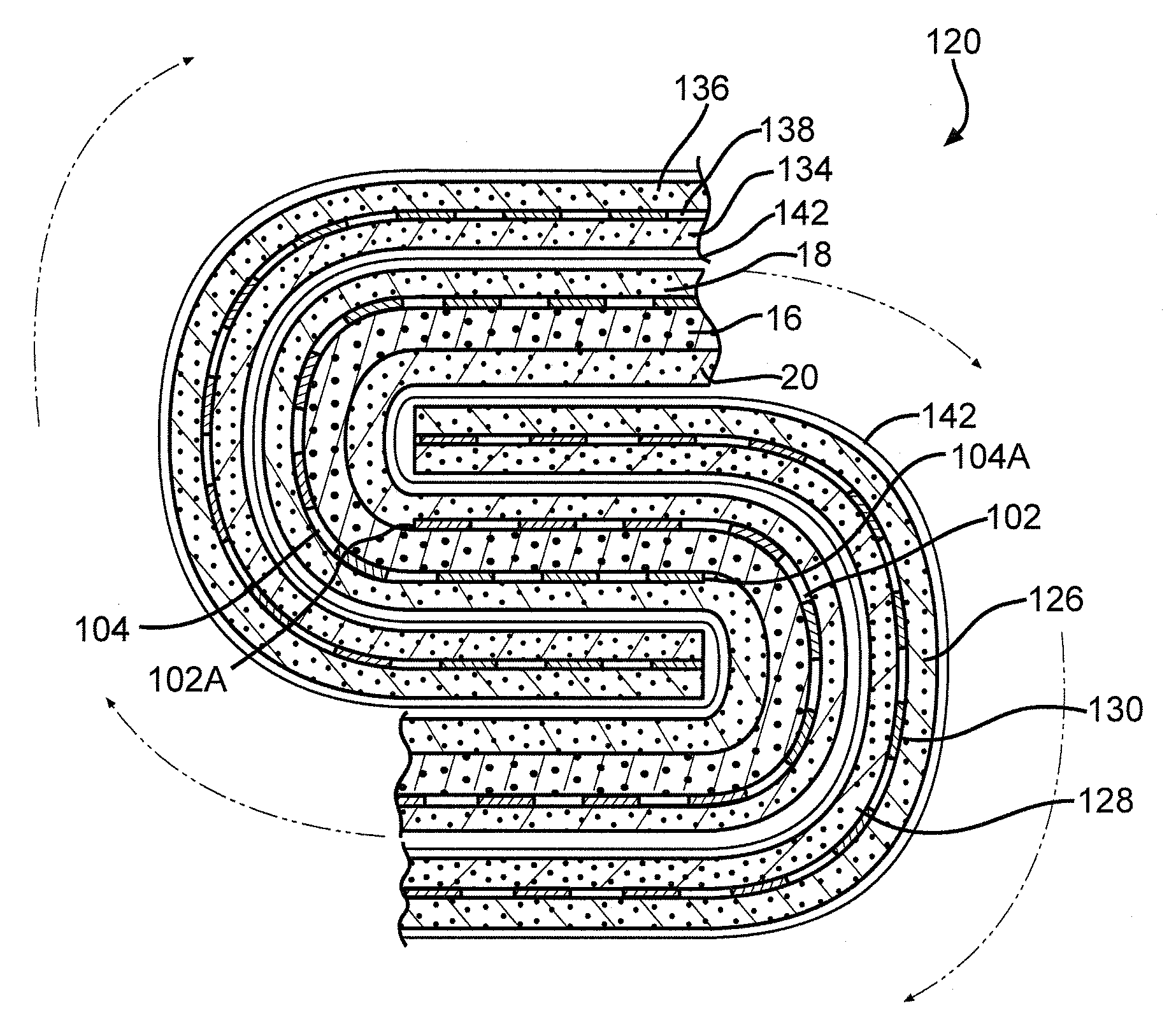
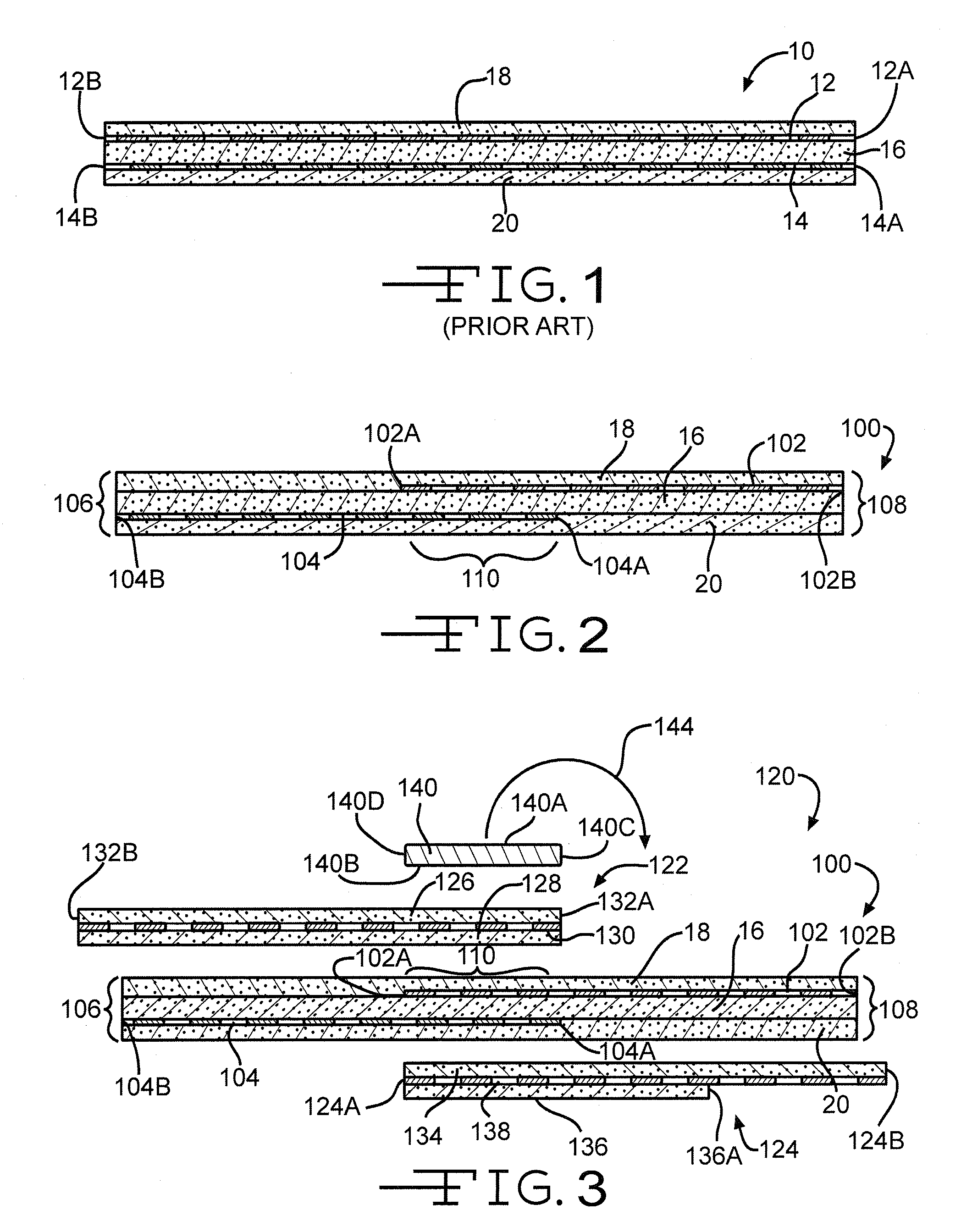
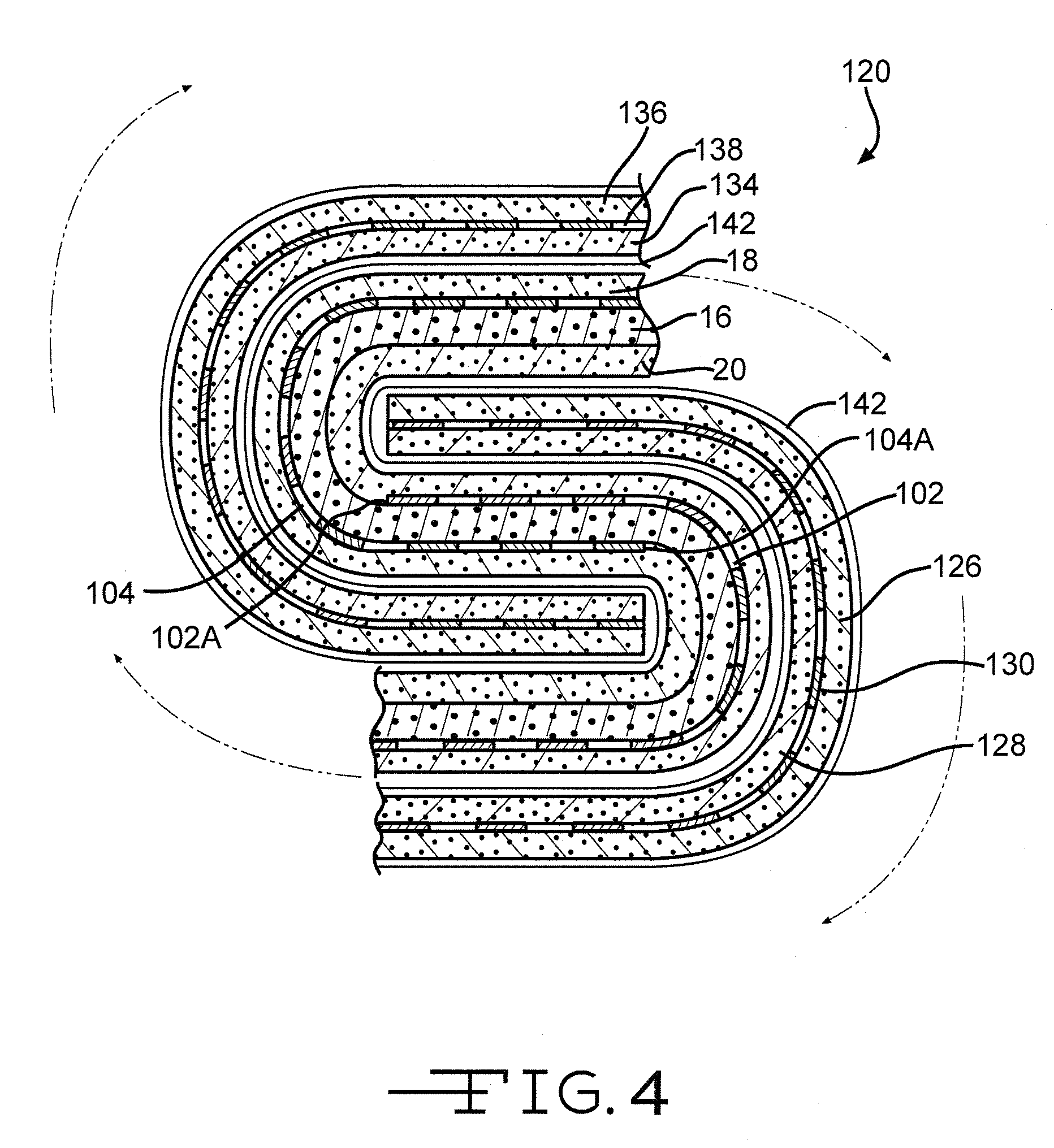
The present invention is about improving the performance of lithium electrochemical cells by using a new design for the cathode. The cathode is made up of two layers of different materials, one layer with high energy density but low rate capability and another layer with low energy density but high rate capability. The two layers are sandwiched between two current collectors. The design also includes two current collectors that are vertically aligned in the middle of the cathode, which helps balance the expansion forces of the two layers and maintain a planar cathode that is easier to process. This design also provides enhanced reliability when winding the cathode. The technical effect of this invention is to improve the performance and reliability of lithium electrochemical cells.

Problems solved by technology

However, plate-type designs are impractical for a wound cell because the current collectors extend the entire length of the active materials.
A cathode comprising two current collectors extending along the entire electrode length cannot be easily wound because the turn radii of two current collectors are not the same.
Consequently, the current collectors tend to separate from the cathode materials causing de-lamination.

Method used


Image

  • Sandwich Cathode Electrochemical Cell With Wound Electrode Assembly
  • Sandwich Cathode Electrochemical Cell With Wound Electrode Assembly
  • Sandwich Cathode Electrochemical Cell With Wound Electrode Assembly

Examples


example

[0050] A cathode assembly was prepared by extruding and rolling SVO material in a matrix of binder and conductive additive to a thickness such that there was 242 mg of SVO per square inch. Similarly, CFx in a matrix of binder and conductive additive was formed to a thickness where there was 205 mg of the active material per square inch. Sheets containing the two materials were punched to provide a blank with surface area equal to 4.51 in2. The active layers were pressed together at about 10 tons / in2 along with two perforated carbon-coated titanium current collectors to provide a cathode of the form SVO / current collector / CFx / current collector / SVO. The total surface area of the electrode assembly was 8.903 in2. The cathode was heat-sealed inside a polyethylene separator.

[0051] Two anode assemblies were prepared by brushing and pressing a lithium ribbon (0.0073″ thick) on either side of a nickel current collector. The two anodes were heat-sealed in polyethylene. The three electrodes (...


PUM

PropertyMeasurementUnit
weight percentaaaaaaaaaa
voltageaaaaaaaaaa

Abstract

A new design for a cathode having a configuration of: SVO / first current collector / CFx / second current collector / SVO is described. The two cathode current collectors are vertically aligned one on top of the other in a middle region or zone of the cathode. This coincides to where a winding mandrel will be positioned to form a wound electrode assembly with an anode. The overlapping region of the two current collectors helps balance the expansion forces of the exemplary SVO and CFx active material layers. This, in turn, helps maintain a planar cathode that is more amenable to downstream processing. The use of two current collectors on opposite sides of an intermediate cathode active material also provides for enhanced reliability when cathodes are wound from the center as they lend structural integrity to outer portions of the wind.

Description

CROSS-REFERENCE TO RELATED APPLICATION [0001] This application claims priority from provisional application Ser. No. 60 / 717,520, filed Sep. 15, 2005.BACKGROUND OF THE INVENTION [0002] 1. Field Of Invention [0003] This invention relates to the conversion of chemical energy to electrical energy. In particular, the present invention relates to a new sandwich cathode design having a first cathode active material of a relatively low energy density but of a relatively high rate capability sandwiched between two current collectors and with a second cathode active material having a relatively high energy density but of a relatively low rate capability in contact with the opposite side of the current collectors. The current collectors are configured so that they only overlay or are vertically aligned one above the other in a middle zone of the electrode assembly. This middle zone extends approximately the same length as a flat winding mandrel that will later be used to wind the sandwich cath...

Claims


Application Information

Patent Timeline
Patent Type & Authority Applications(United States)
IPC IPC(8): H01M4/02H01M4/58H01M4/50H01M4/52H01M4/66H01M4/54H01M10/04H01M10/0585H01M10/38
CPCH01M4/136H01M4/366H01M4/54H01M4/5825H01M4/661H01M4/667Y10T29/49108H01M10/052H01M10/0568H01M10/0569H01M10/0583H01M10/0585Y02E60/122H01M10/0431Y02E60/10Y02P70/50
Inventor RUBINO, ROBERT S.GAN, HONGTAKEUCHI, ESTHER S.
Owner WILSON GREATBATCH LTD
Learn More