Cordless LED light driving wall module and night light

a technology of led light and driving wall, which is applied in the direction of signalling/lighting devices, textiles, paper, etc., and can solve the problem that users will need to turn off the ligh

Inactive Publication Date: 2004-08-19
PLASTICS INVENTIONS & PATENTS INC
View PDF13 Cites 44 Cited by
  • Summary
  • Abstract
  • Description
  • Claims
  • Application Information

AI Technical Summary

Benefits of technology

0015] It is an object of the invention to provide improved elements and arrangements thereof in an apparatus for t

Problems solved by technology

These lights have historically used a low wattage bulb capable of being plugged in and lit 24 hours per day seven days per week, with just e

Method used


Image

  • Cordless LED light driving wall module and night light
  • Cordless LED light driving wall module and night light
  • Cordless LED light driving wall module and night light

Examples


first embodiment

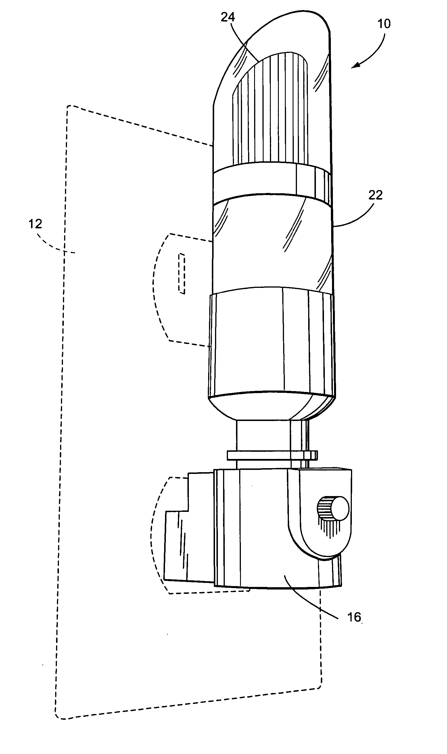
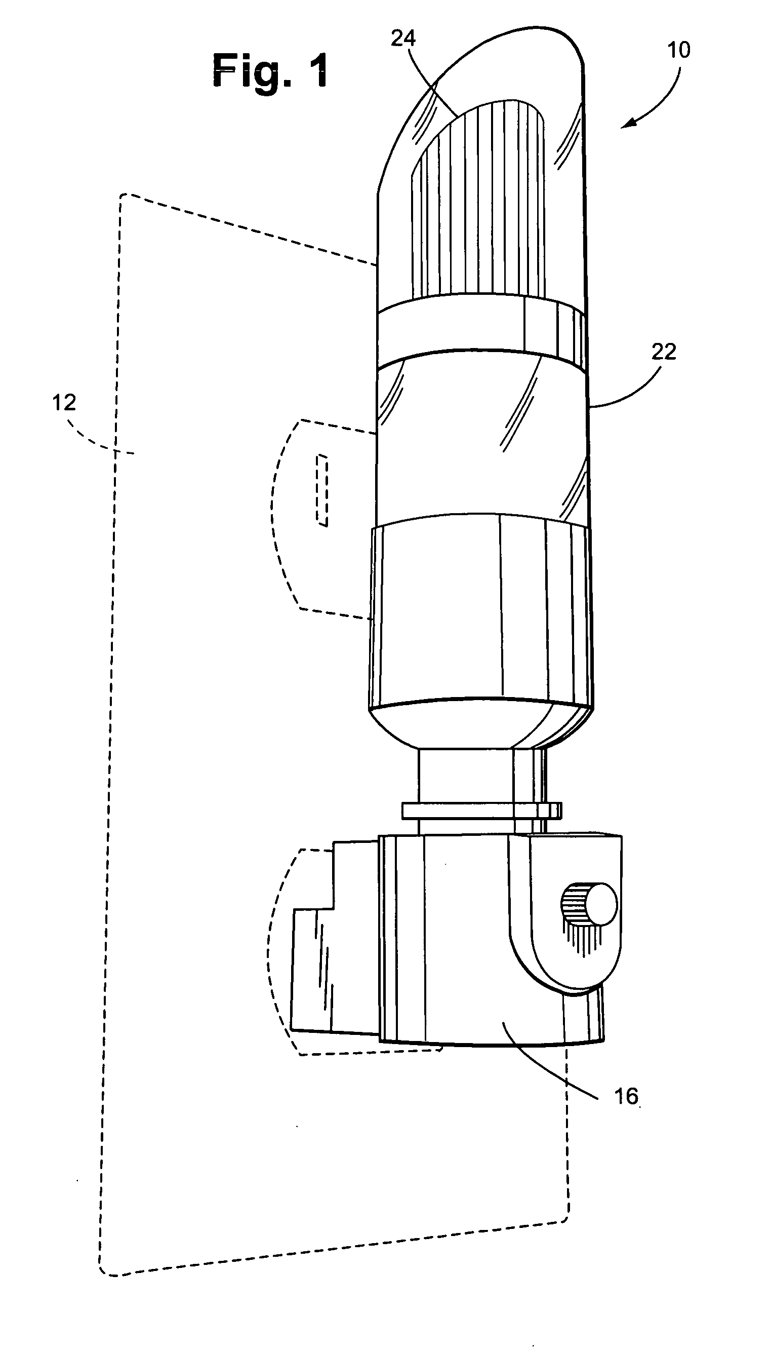
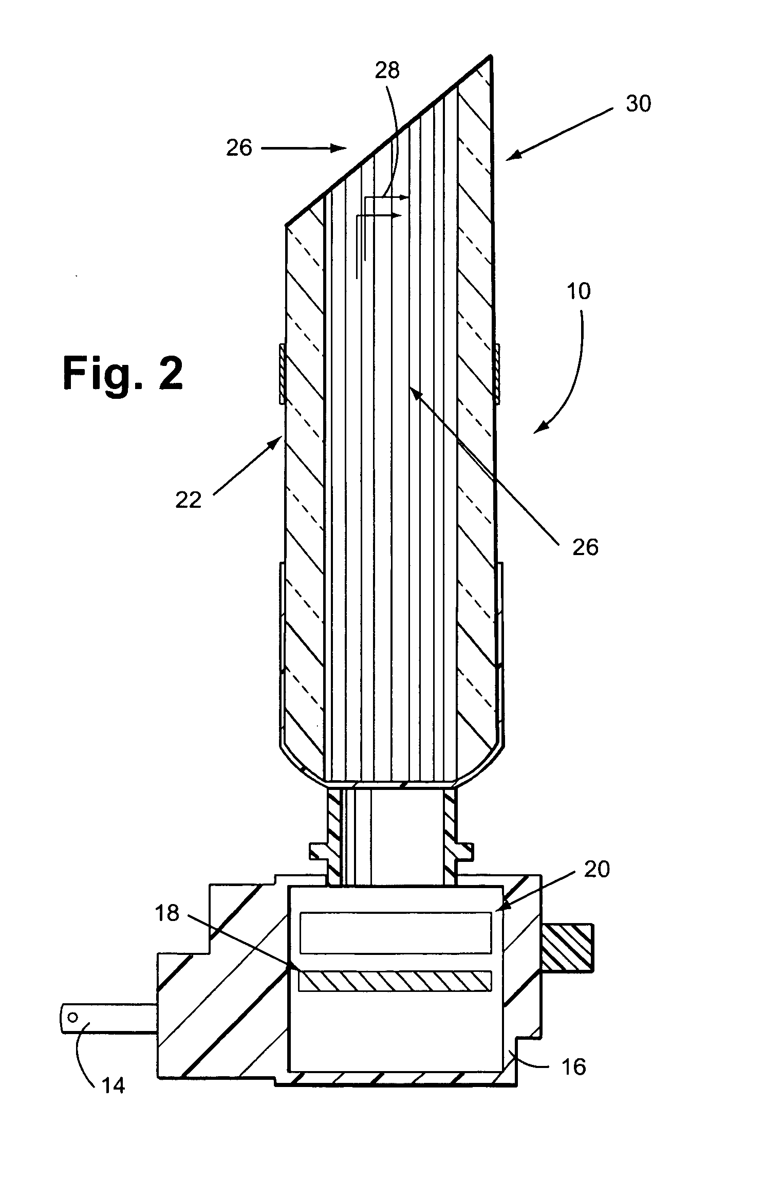
[0023] The present invention to methods of providing decorative and useful lighting which utilize low power consumption and safer LED lighting. The first embodiment shown in FIGS. 1 and 2 shows a nightlight 10. The nightlight is sized to plug into a standard electrical wall outlet 12 through the nightlight's plugs 14. As is known in the art, the nightlight is suspended from the electrical wall outlet by the prongs ("plugs") 14. The nightlight must be light enough and stand close enough to the wall to remain suspended from the outlet without falling out. The plugs 14 extend outwardly from a base 16 and are electrically connected to a step down circuit board 18. The step down transformer (not shown) steps the AC voltage down to a low AC voltage which is then rectified to a low DC voltage, preferably in the range of 2.0 to 4.0 volts suitable for driving L.E.D.'s.

[0024] The output of the step down circuit is connected to a super bright L.E.D. 20 such as a LUXEON L.E.D. or a clustered 5 ...

second embodiment

[0031] Second Embodiment

[0032] The second embodiment shown in FIGS. 3 & 4 of a decorative light system 100 takes further advantage of fiber optics to provide decorative, flexible lighting. A non-conductive base unit 116 has an opaque shell housing electrical plugs 114 for connecting to an electrical outlet (not shown). Alternatively or additionally the base unit can be connected to an electrical source through an external step down transformer 117 or other means well known in the art such as batteries or other AC sources.

[0033] Once the voltage is stepped down and converted to DC, the circuit is connected to an LED or group of LEDs to provide a light driver for optionally connected fiber optic carriers. A Y splitter is provided to split the light from the LED source into two port connections. Of course one skilled in the art would recognize that the ports could each be lit by separate LEDs or groups of LEDs without parting from the scope of the invention. However, preferably a Y sha...

third embodiment

[0040] Third Embodiment

[0041] A further application of a fiber optic light driver is shown in FIG. 5. Since the fiber optic light is "cold", that is non-electric carrying and non-heat carrying, the light can used in an aqueous environment. As shown in FIG. 5, the light driver 200 can connect to a fiber optic strand 240 that connects to and runs inside of a garden hose 150, kitchen sink faucets, or other liquid conduit. Appropriate Y connectors and seals can be used to ensure that liquid does not leak from the connection as is known to those skilled in the art. Likewise the light driver 200 can be housed in an all weather housing to withstand outdoor unwanted elements.

[0042] If the fiber optic strand 240 has an opaque housing then the light will be transported to the end of the strand. By placing the end of the strand at the end ("mouth") of the hose, the light can be used to illuminate where the hose is pointing. This can be used for practical purposes such as watering plants in poo...


PUM

PropertyMeasurementUnit
Angleaaaaaaaaaa
Volumeaaaaaaaaaa
Electric potential / voltageaaaaaaaaaa

Abstract

A novel lighting system utilizing low power consumption LEDs to provide safe, economical and decorative lighting. In a first embodiment, and acrylic candle body having a 45 degree reflector is mounted on top of a LED source to direct light along the body of the light and outwardly as directed by the reflector. The acrylic body can be rotated to point the reflected light in the desired direction. In a second embodiment, the acrylic candle and reflector are replaced by fiber optic ports and a light driver for connecting fiber optic strands that can be side lighting or end lighting to provide lighting at points distant from the light source. In a third embodiment, the fiber optic strand in run in parallel inside or outside a transparent liquid conduit such as a modified garden hose, a beverage dispenser, or a kitchen faucet to light the conduit and or the spray of the hose in a single or multiple colors.

Description

[0001] This application claims the benefit of U.S. Provisional Application 60 / 416,824, filed Oct. 8, 2003, entitled Cordless LED Light Driving Wall Module, which is hereby incorporated by reference. This application also claims the benefit of U.S. Provisional Application 60 / 418,567, filed Oct. 16, 2003, entitled Acrylic Night Light, which is hereby incorporated by reference and Provisional Application 60 / 418,264, filed Oct. 15, 2003, entitled Illuminated Fluid, which is also hereby incorporated by reference[0002] 1. Field of the Invention[0003] The present invention relates to a fiber optic light driving module and a method of providing a decorative night lighting system.[0004] 2. Description of the Prior Art[0005] Children's rooms, hallways and bathrooms have frequently been the location of night lights. The lighting is well known to many families with small children and others who get up during the night and want to be able to see well enough to traverse a hallway or locate a wall...

Claims


Application Information

Patent Timeline
IPC IPC(8): F21S8/00F21S10/00F21V8/00F21V33/00
CPCF21S8/035F21S10/005G02B6/0008F21Y2101/02F21V33/004F21Y2115/10
Inventor CURRIE, ROBERT M.ROBERTSON, JONAS J.
Owner PLASTICS INVENTIONS & PATENTS INC
Why Eureka
Try Eureka