Supercharge Your Innovation With Domain-Expert AI Agents!

Magnetic head for perpendicular recording and magnetic disk storage apparatus mounting the head

a magnetic disk storage and perpendicular recording technology, applied in the direction of heads with metal sheet cores, special recording techniques, instruments, etc., can solve the problems of thermal fluctuation loss of recording written magnetization on a medium, difficulty in enhancing recording density, and disturb writing bits written

Inactive Publication Date: 2004-09-23
MOCHIZUKI MASAFUMI +2
View PDF16 Cites 8 Cited by
  • Summary
  • Abstract
  • Description
  • Claims
  • Application Information

AI Technical Summary

Problems solved by technology

In the longitudinal magnetic recording system, however, a smaller recording bit disadvantageously causes a recording written magnetization on a medium to be lost by thermal fluctuation.
This disadvantage brings about difficulty in enhancing the recording density.
The provision of the soft under layer leads to increasing a writing magnetic field strength obtained by the write head but also leads disadvantageously to giving rise to a failure caused by the under layer itself.
This change brings about a magnetic field, which may disturb the writing bits written on the recording layer or be observed as noise when reading the magnetizing signal with a read element.
Moreover, a certain kind of distribution of the change of magnetization may bring about a large magnetic field from the under layer.
The magnetic field caused by the change of magnetization of the under layer, which may disadvantageously disturb the magnetization signal written on a recording layer or be observed as noise when reading the magnetization signal with the read element, leads to a great obstacle in realizing high-density recording.

Method used


Image

  • Magnetic head for perpendicular recording and magnetic disk storage apparatus mounting the head
  • Magnetic head for perpendicular recording and magnetic disk storage apparatus mounting the head
  • Magnetic head for perpendicular recording and magnetic disk storage apparatus mounting the head

Examples


first embodiment

[0030] (First Embodiment)

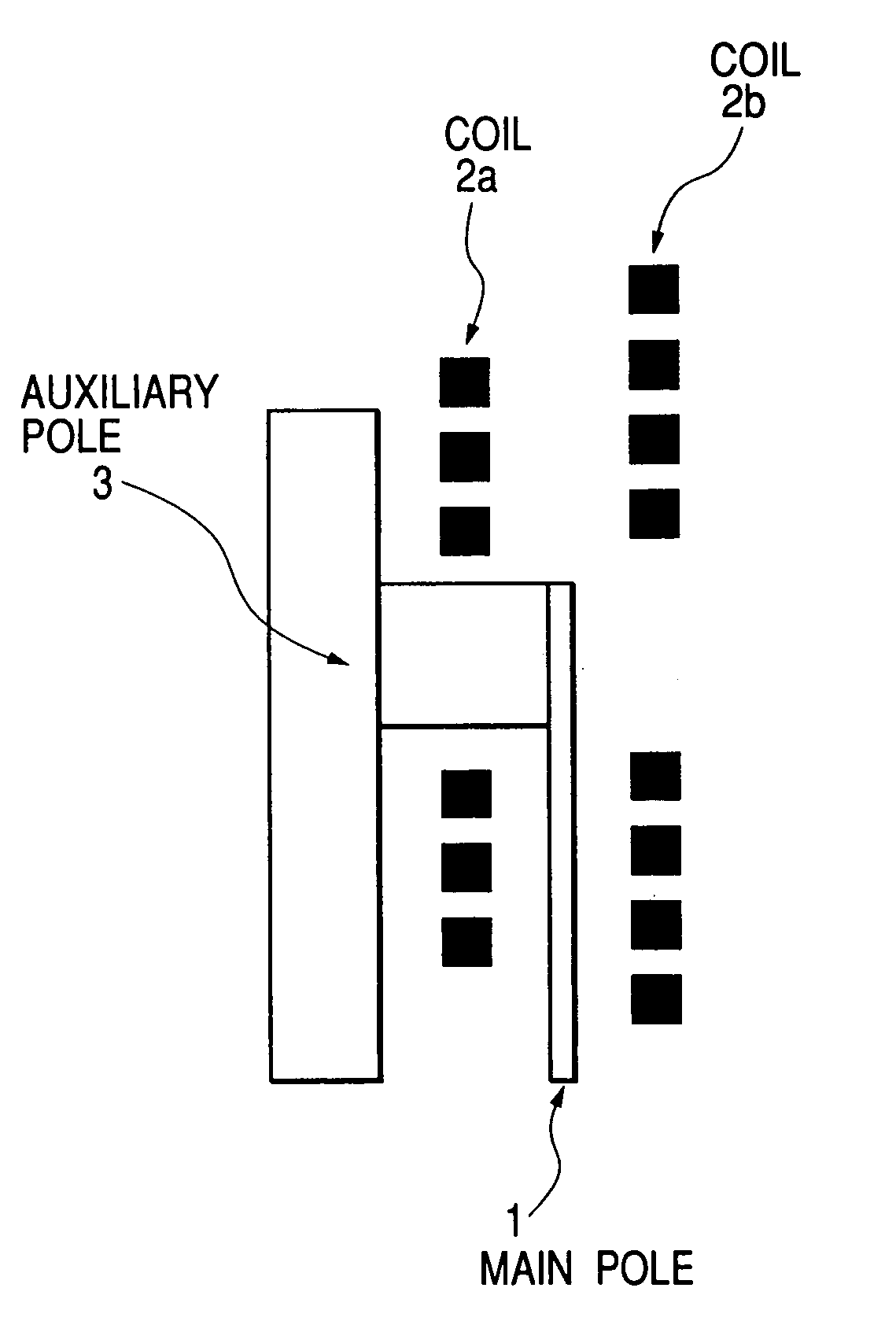
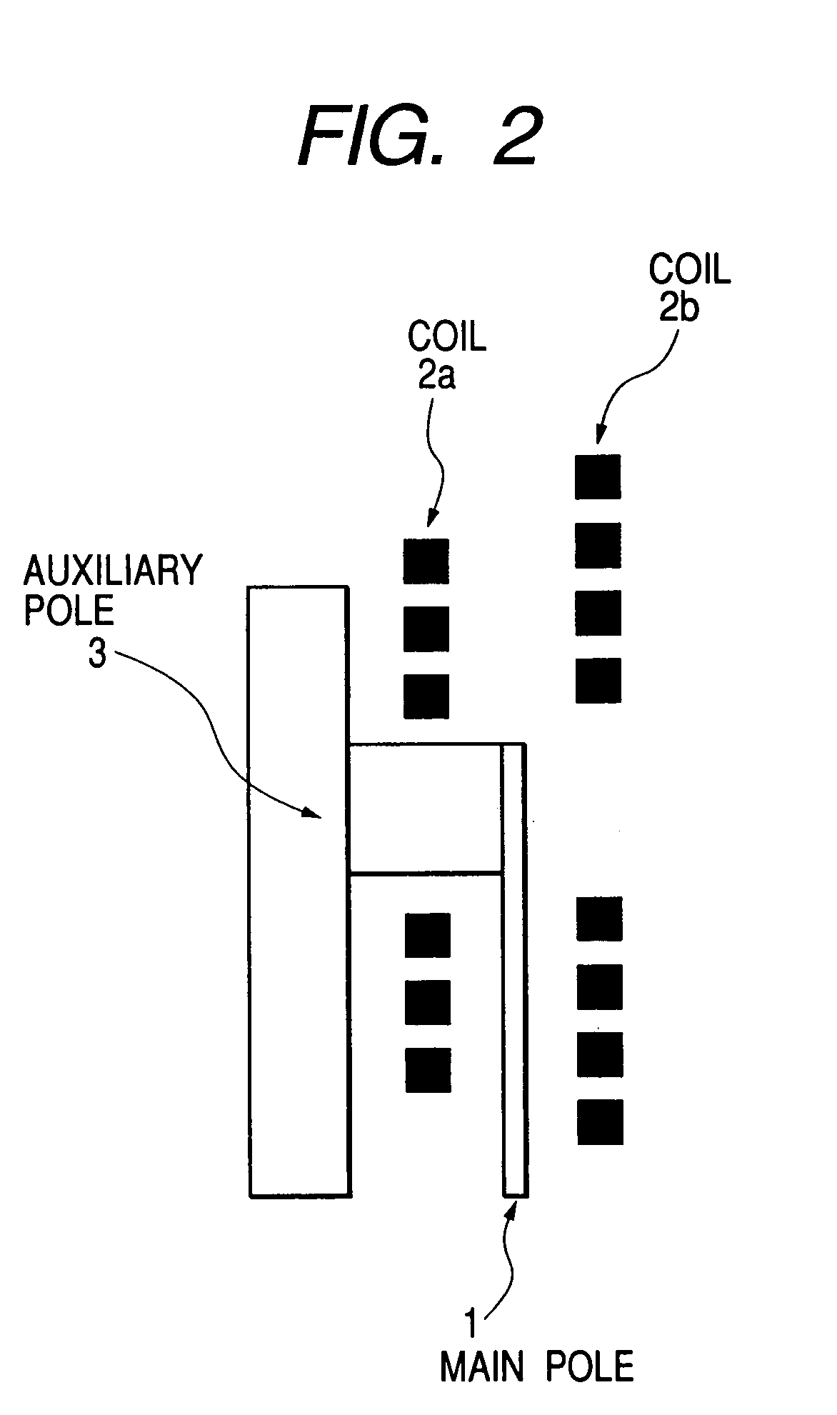
[0031] FIG. 2 is a sectional model view showing the first embodiment of a single pole type write head used in the present invention. In this embodiment, the write head is composed of a main pole 1, an auxiliary pole 3 and thin-film conductor coils 2a and 2b located on both sides of the main pole 1 in a manner to sandwich the main pole 1. The schematic model view of FIG. 2 sectionally illustrates the magnetic head in the disk rotating direction from the center of the disk track, in which view the magnification factors are not unified. The two coils 2a and 2b may be composed so as to be connected in the disk rotating direction so that a magnetic field of the same polarity may be generated at the tip of the main pole 1. Or, these coils 2a and 2b may be composed to separate these coils 2a and 2b from each other so that each coil generates the magnetic field of the same polarity at the tip thereof.

[0032] As is obvious from FIG. 2, in this embodiment, the number o...

second embodiment

[0040] (Second Embodiment)

[0041] FIGS. 7A, 7B show the magnetic head according to the second embodiment of the invention. The views of these figures show the magnetic flux density distribution in the case that the distance D1 between the main pole 1 and the auxiliary pole 3 (that is, the distance between the opposed side of the main pole 1 to the auxiliary pole 3 and the opposed side of the auxiliary pole 3 to the main pole) is changed into 3 .mu.m, for comparing the head of the conventional structure (see FIG. 7A) with the single pole type head of the present invention (see FIG. 7B). In the conventional structure shown in FIG. 7A, by narrowing the distance D1 more than the distance D1 of 15 .mu.m, the distribution of a greater magnetic flux density is made wider. On the other hand, in the head structure of the invention shown in FIG. 7B, even if the distance D1 between the main pole 1 and the auxiliary pole 3 is made narrower, the magnetic flux density of the under layer 20 is made...

third embodiment

[0044] (Third Embodiment)

[0045] FIG. 9 is a schematic sectional view showing a magnetic head according to a third embodiment of the present invention, in which view the read element 7 and the auxiliary pole 3 are located in a manner to sandwich the main pole 1 and the coils are located on both sides of the main pole in an asymmetrical manner, that is, in a manner to apply respective magneto-motive forces onto both sides of the main pole as described with respect to the foregoing first and second embodiments. The section is cut on the center of the track in the disk rotating direction.

[0046] In this embodiment, no auxiliary pole 3 is provided between the read element 7 and the main pole 1, so that the distance D3 between the read element 7 and the opposed side of the main pole 1 to the read element 7 may be made narrower by the film thickness. Moreover, since the magnetic flux being flown from the main pole 1 to the upper shield 9 is suppressed, it is preferable to make the distance ...


PUM

PropertyMeasurementUnit
magnetic flux densityaaaaaaaaaa

Abstract

A magnetic head is composed to diminish disordered writing bits of a recording layer or reading noise caused by a magnetic field generated from an under layer without decreasing a writing magnetic field strength of the magnetic head. The magnetic head includes a write head provided with a main pole and one or more auxiliary poles, a read head provided with a read element, and coils located on both sides of the main pole in a manner to sandwich the main pole. The coil located on one side generates the asymmetrical magneto-motive force for magnetizing the main pole to that generated by the coil located on the other side.

Description

[0001] 1. Field of the Invention[0002] The present invention relates to a magnetic head for perpendicular recording and a magnetic disk storage apparatus provided with the head mounted thereon.[0003] 2. Description of the Related Art[0004] In general, the magnetic disk storage apparatus is composed so that data may be read or written on a recording medium by using a magnetic head. In order to increase a recording density per a unit area of a magnetic disk, it is necessary to decrease a size of recording bit. In the longitudinal magnetic recording system, however, a smaller recording bit disadvantageously causes a recording written magnetization on a medium to be lost by thermal fluctuation. This disadvantage brings about difficulty in enhancing the recording density. As the effective technique in overcoming this difficulty, the perpendicular recording system may be referred which is composed to record (or write) the magnetization in the perpendicular direction to the medium.[0005] T...

Claims


Application Information

Patent Timeline
Patent Type & Authority Applications(United States)
IPC IPC(8): G11B5/667G11B5/00G11B5/127G11B5/147G11B5/17G11B5/265G11B5/31G11B5/33G11B5/39
CPCB82Y10/00G11B2005/3996G11B5/1278G11B5/17G11B5/2652G11B5/313G11B5/332G11B5/3903G11B5/3909G11B5/3967G11B2005/001G11B2005/0013G11B2005/0016G11B2005/0029B82Y25/00
Inventor MOCHIZUKI, MASAFUMINAKAMURA, ATSUSHIMARUYAMA, YOJI
Owner MOCHIZUKI MASAFUMI
Features
  • R&D
  • Intellectual Property
  • Life Sciences
  • Materials
  • Tech Scout
  • Unparalleled Data Quality
  • Higher Quality Content
  • 60% Fewer Hallucinations
Learn More