
Control dial and optical disk apparatus having the control dial

a technology of optical disk and control dial, which is applied in the direction of record information storage, instruments, detergent compounding agents, etc., can solve the problems of affecting the operability of the dial, wasting time in searching for the precise position of the target to be reproduced, and causing excessive movement of the jog dial, etc., to achieve faster and precise positioning, and eliminate erroneous motion

Inactive Publication Date: 2004-10-21
DENON
View PDF15 Cites 11 Cited by
  • Summary
  • Abstract
  • Description
  • Claims
  • Application Information

AI Technical Summary

Benefits of technology

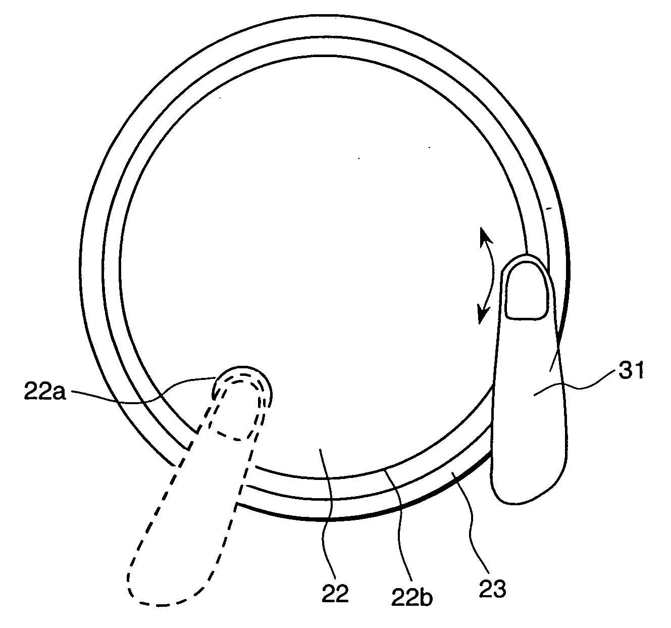
[0013] An object of the present invention is to provide for an optical disk apparatus which features a unique structure of a control dial which ensures for its jog dial to be adjusted by motion of the forefinger of the user without touching the shuttle dial which is disposed outside the jog dial and in proximity thereof thereby eliminating erroneous motion thereof, and also ensures that a faster and precise positioning is achieved for its optical pickup at the position of a target of recorded information to be reproduced.

Problems solved by technology

In the above-mentioned optical disk apparatus provided with the shuttle dial and the jog dial, when rotating its jog dial by placing the forefinger on the dent thereof in order to determine the position of the target of recorded information to be reproduced, there often occurs an excess movement of the jog dial, thereby taking too much time in searching of the precise position of the target to be reproduced.
Further, because the position of the dent thereof is not always at a preferred position, which is easy for the forefinger to operate, operability thereof is often impaired.
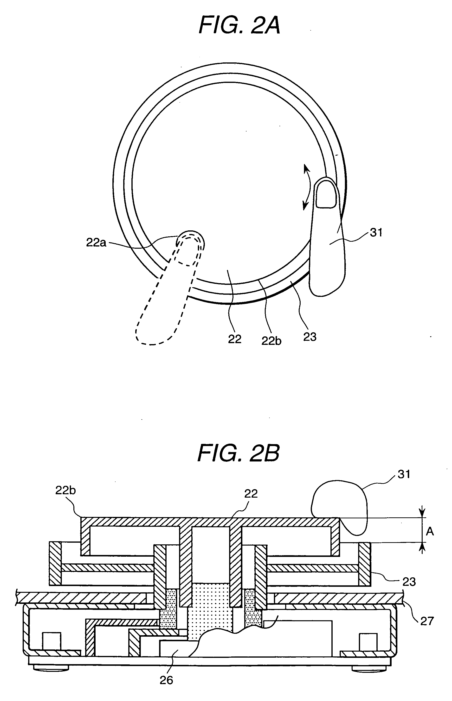
However, there occurs such a problem that-when the jog dial is operated by the forefinger that is placed at the peripheral corner of the upper surface of the jog dial, the forefinger easily makes contact also with the shuttle dial which is arranged outside the jog dial in proximity thereof thereby unintentionally moving the shuttle dial together with the jog dial, and thereby rendering it difficult to achieve a faster and precise positioning of the optical pickup at the position of the target of recorded information which is desired to be reproduced.

Method used


Image

  • Control dial and optical disk apparatus having the control dial
  • Control dial and optical disk apparatus having the control dial
  • Control dial and optical disk apparatus having the control dial

Examples


Embodiment Construction

[0018] An optical disk apparatus according to one preferred embodiment of the invention will be described with reference to the accompanying drawings in the following.

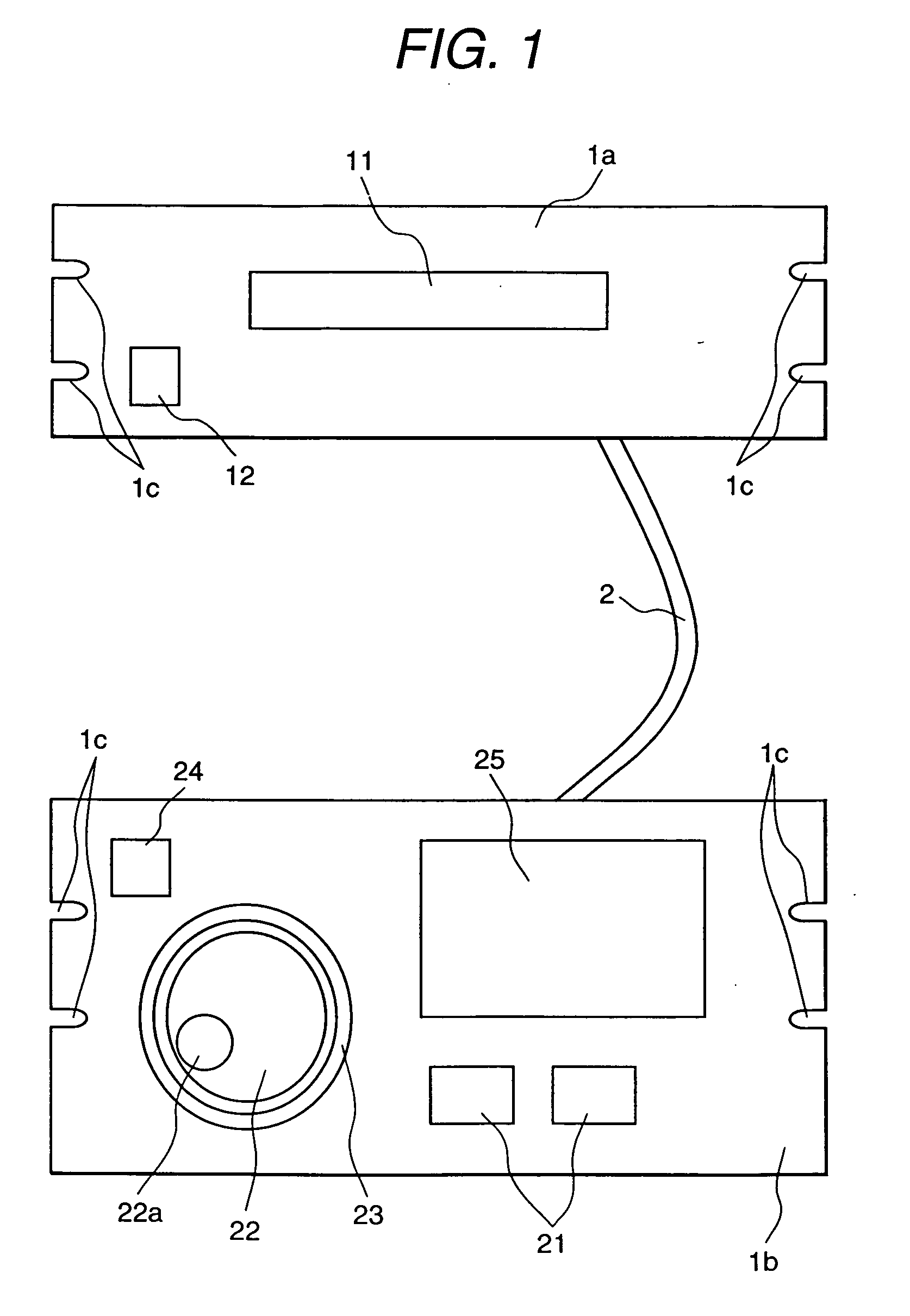
[0019] FIG. 1 is a schematic block diagram indicating the optical disk apparatus of the invention.

[0020] Optical disk apparatus 1 in FIG. 1 is comprised of a main body 1a and a control device 1b thereof which is connected to the main body 1a via a control line 2, for controlling the operation of the main body 1a.

[0021] Main body 1a and control device 1b thereof have mounting opening 1c provided in their front panels for mounting in a rack (not shown).

[0022] The main body 1a has: a loading tray 11 for loading an optical disk; a reproduction unit (not shown) for reproducing information which is recorded in the optical disk which is loaded through the loading tray and mounted on a turn table via an optical pickup; an output terminal (not shown) for outputting an audio signal which is reproduced by the reproduction unit; a...


PUM


Abstract

An optical disk apparatus comprising a control dial unit having a jog dial and a shuttle dial which is concentrically mounted outside the jog dial is provided to solve the problem that when operating the jog dial, the shuttle dial in proximity of the jog dial is also rotated thereby preventing its optical pickup to access to a precise target position to be reproduced. The control dial of the invention is comprised of an outer control dial and an inner control dial which has a smaller diameter than the outer control dial and is arranged within a circumference of the outer control dial, wherein a peripheral corner of an upper surface of the inner control dial protrudes from an upper surface of the outer control dial, and its distance of protrusion is larger than 2 mm and smaller than 90 mm.

Description

[0001] The present invention relates to a control dial for controlling reproduction operation of an optical disk apparatus and an optical disk apparatus having the control dial.[0002] There are optical disk apparatus which are provided with a control dial which include a jog dial and a shuttle dial which are used for editing video data or the like. For example, one of such-apparatus is disclosed in JPA No.11-111118.[0003] Generally, in this control dial, its jog dial and shuttle dial are arranged coaxially with concentrical axes of rotation. Further, its control dial in which its shuttle dial is arranged externally outside the periphery of its jog dial is provided on a front panel of the optical disk apparatus.[0004] Directions of traverse of an optical pickup, which traces tracks on an optical disk in search of information for reproduction, can be changed by changing a direction of rotation of the shuttle dial. The optical disk apparatus can execute a rapid forward or reverse direc...

Claims


Application Information

Patent Timeline
IPC IPC(8): G11B15/10G11B19/02G11B19/16H01H19/00H01H19/14
CPCC11D3/0084G11B15/106G11B19/022G11B19/16H01H19/005H01H19/14
Inventor HORI, MASAYUKI
Owner DENON
Learn More