Surveillance system and surveillance method with cooperative surveillance terminals

a cooperative surveillance and surveillance system technology, applied in the field of surveillance system and surveillance method, can solve the problems of not strengthening surveillance and collecting related data, surveillance setup cannot be arranged immediately and the surveillance setup for the moving hazard source cannot be strengthened

Inactive Publication Date: 2004-10-28
HITACHI LTD
View PDF4 Cites 24 Cited by
  • Summary
  • Abstract
  • Description
  • Claims
  • Application Information

AI Technical Summary

Problems solved by technology

To other surveillance terminals, the surveillance center simply sends a hazard signal, but does not strengthen the surveillance and collect related data.
Therefore, if the hazard source moves, the surveillance setup cannot be arranged immediately for the moving hazard source.
In other words, before another event of the same hazard arises in another area in the vicinity of the hazard locality, the surveillance setup for the moving hazard source cannot be strengthened.
In surrounding areas on the initial hazard locality, there is a possibility of chain reaction happening of the same hazard, and this is a problem in security.

Method used


Image

  • Surveillance system and surveillance method with cooperative surveillance terminals
  • Surveillance system and surveillance method with cooperative surveillance terminals
  • Surveillance system and surveillance method with cooperative surveillance terminals

Examples


embodiment 1

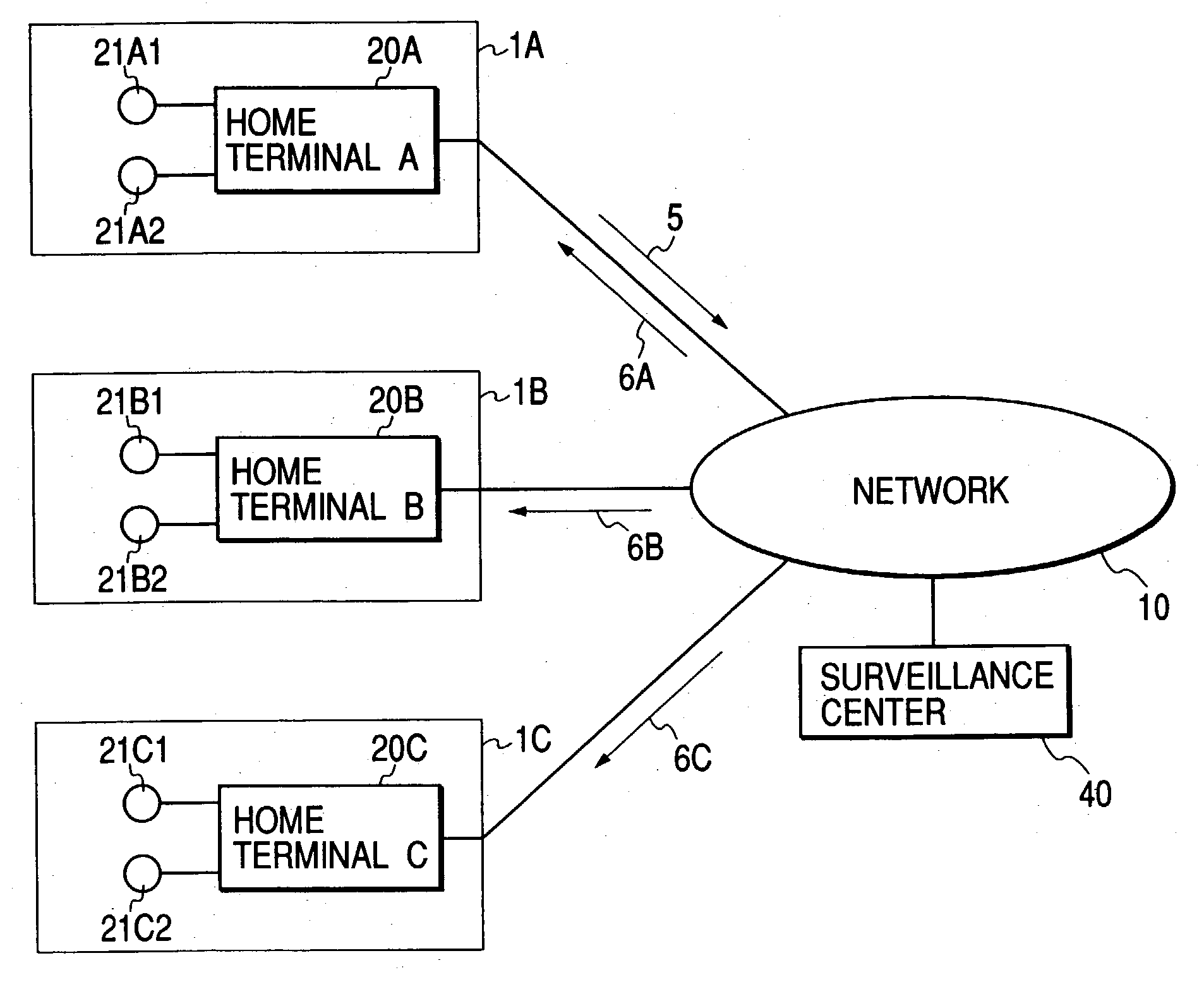
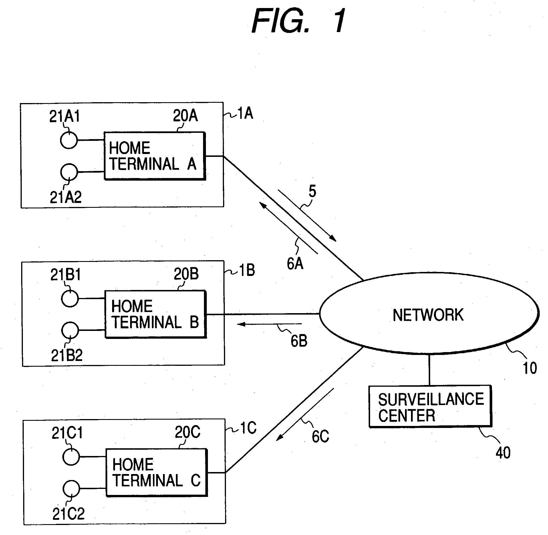
[0023] The cooperative surveillance system of Embodiment 1 includes three homes 1A, 1B, 1C, each equipped with two surveillance cameras. In this system, cooperative surveillance is performed among the three homes. Equipment in home 1A consists of surveillance cameras 21A1 and 21A2 and a home terminal 20A. The surveillance cameras 21A capture the views around them and send video data of the views to the home terminal 20A. The home terminal 20A analyzes the video data and, if the video data meets predetermined conditions of hazard detection, sends a hazard signal 100 to the surveillance center over the network 10.

[0024] Equipment in home 1B consists of surveillance cameras 21B1 and 21B2 and a home terminal 20B. Equipment in home 1C consists of surveillance cameras 21C1 and 21C2 and a home terminal 20C. These equipments also operate as described for the equipment in home 1A.

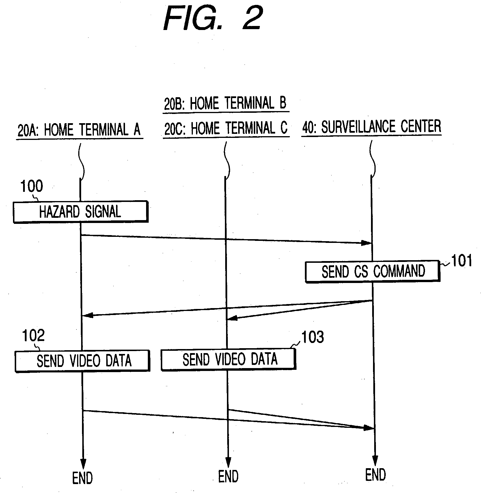
[0025] Referring to FIG. 2, signaling in the system of Embodiment 1 will be explained for a case where a hazard h...

embodiment 2

[0032] Referring to FIG. 4, signaling in the system of Embodiment 2 will be explained for a case where a hazard has occurred in home 1A. When a hazard occurring is detected in home 1A, the home terminal 20A sends a hazard signal 100 to the surveillance center 40. Upon the detection of the hazard occurrence, the surveillance center 40 sends a cooperative surveillance command 101 to not only home 1A where the hazard has just occurred, also homes 1B and 1C in the vicinity of the home 1A and the outside terminal 3D installed in the neighborhood of these homes. When the home terminals 20A, 20B, 20C, and the outside terminal 3D receive cooperative surveillance commands, respectively, they send video data 102, 103 to the surveillance center 40 through the network 10. The video data is the video data of the views captured by the surveillance cameras 21A1, 21A2, 21B1, 21B2, 21C1, 21C2 for the home terminals and the surveillance camera 31D1 connected to the home terminal 3D. Based on the vide...

embodiment 3

[0037] In the system of Embodiment 3, essentially, cooperative surveillance is performed among three homes 1A, 1B, 1C with their surveillance cameras and the outside surveillance camera equipment 3D. In addition, terminals that can receive data and are respectively used by the ones who live in the homes 1A, 1B, 1C, but are not home now, namely, user terminals 50A, 50B, 50C are connected to the network 10. Examples of the user terminals 50A, 50B, 50C are personal computers and mobile phones which are wired or wirelessly connected to the network 10. Equipment configurations and operation at the homes 1A, 1B, 1C, and the operation of the outside terminal 3D are the same as described in the foregoing embodiments.

[0038] In the system of Embodiment 3, for example, when a hazard occurs in home 1A, the surveillance center 40 sends a cooperative surveillance command 101 to the home 1A, homes 1B, 1C in its vicinity, and outside terminal 3D. In addition, the surveillance center 40 sends a haza...


PUM


Abstract

The present invention provides a system and method of surveillance to support an early intensive surveillance setup in surrounding areas on the locality of a hazard. A surveillance system of the present invention comprises two or more surveillance terminals and a surveillance center to which the surveillance terminals are connected via a network. Each surveillance terminal comprises a hazard detecting unit, a hazard signal sending unit, and a video data sending unit. The surveillance center comprises a unit for detecting a hazard signal from one or more of the surveillance terminals and a command sending unit for sending a surveillance command to the two or more surveillance terminals. In response to a hazard occurring, the surveillance center changes a surveillance setup of a surveillance terminal which has just detected the hazard and surveillance terminals falling in surrounding areas on the hazard locality, so that target zonal cooperative surveillance is performed.

Description

[0001] 1. Field of the Invention[0002] The present invention relates to a system and method of surveillance to detect the occurrence of a hazard of crime, calamities, etc. and alert residents in the locality of the hazard and its vicinity.[0003] 2. Description of the Related Art[0004] In a prior art surveillance system where one ore more surveillance terminals with surveillance camera equipment are networked to a surveillance center, the surveillance center performs the surveillance control, using discrete links to each surveillance terminal. For example, when a surveillance terminal detects a hazard occurring, the surveillance center obtains information in various aspects of the hazard from the surveillance terminal that detected the hazard and strengthens the local surveillance (for example, refer to Kokai, Japanese Unexamined Patent Publication No. 2000-316146). Also, upon the detection of a hazard occurring, the surveillance center alerts residents in the locality of the hazard ...

Claims


Application Information

Patent Timeline
Patent Type & Authority Applications(United States)
IPC IPC(8): E04B1/682E04B1/61E04C5/10E04G21/12H04N7/18
CPCG08B13/19645G08B13/19669G08B13/19697H04N7/181
Inventor INATA, KEISUKENAKAMURA, TAKU
Owner HITACHI LTD
Why Eureka
Try Eureka