Method for performing packet flooding at wireless ad hoc network

a wireless ad hoc network and packet flooding technology, applied in data switching networks, high-level techniques, frequency-division multiplex, etc., can solve problems such as more frequent collisions, difficult installation of wired equipment, and source not always reaching the destination directly

Active Publication Date: 2004-11-04
SAMSUNG ELECTRONICS CO LTD
View PDF3 Cites 55 Cited by
  • Summary
  • Abstract
  • Description
  • Claims
  • Application Information

AI Technical Summary

Problems solved by technology

The small-scale wireless communication network is especially demanded in areas such as inside of a building or in a mountain, where wired equipment is difficult to install.
In a wireless ad hoc network, due to limited transmission range of the wireless frequency of the respective nodes, packets from the source do not always reach the destination directly.
Accordingly, collisions more frequently occur in a complex network, delaying packet transmission of the nodes and subsequently delaying the overall transmission in the network.
Power consumption of the network also increases.
The collision at the MAC layer also impedes finding out the optimum route in the upper layer routing protocol.
As the neighboring nodes of the broadcasting node, which is the source node, try to use the shared channel to re-flood the received nodes at the same time, there occur frequent collisions.
The network having nodes in higher density have more serious problems.
Accordingly, the same packet is re-flooded from the neighboring nodes of the source node unnecessarily many times, resulting in waste of network resources.
Further, if collisions occur due to repetitive attempts of re-flooding, the respective neighboring nodes have to delay the packet transmission for a random period of time until the re-transmission.
As a result, packet transmission is delayed, and power consumption of the respective nodes increases.

Method used


Image

  • Method for performing packet flooding at wireless ad hoc network
  • Method for performing packet flooding at wireless ad hoc network
  • Method for performing packet flooding at wireless ad hoc network

Examples


Embodiment Construction

[0034] Hereinafter, the present invention will be described in detail with reference to several preferred embodiments and the accompanying drawings.

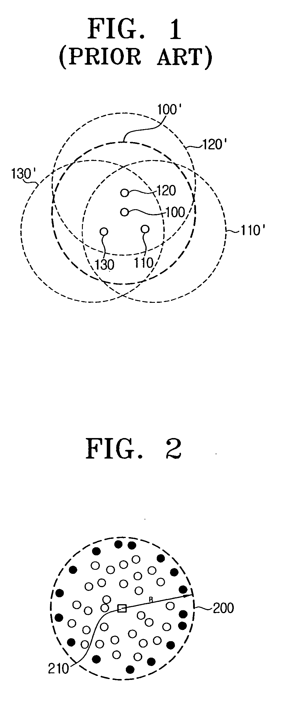
[0035] FIG. 2 is a view of an ad hoc network, for illustrating a method for performing packet flooding according to an exemplary embodiment of the present invention.

[0036] In FIG. 2, there are plural black or white dots within a circle 200. The circle 200 corresponds to the transmission range R of a source node 210.

[0037] If all the nodes within the circle 200, i.e., within the transmission range R perform the packet flooding, problems such as overlaying flooding, collisions and delay in transmission occur. Conventionally, all the neighboring nodes of the source node perform the packet flooding if the packet they received from the source node is the first packet. Accordingly, packets are repeatedly transmitted in transmission ranges of the neighboring nodes which are overlaying many times. If this occurs, collisions and subsequent transm...


PUM


Abstract

A method for packet re-flooding in a wireless ad hoc network for transmitting a broadcast packet from a source node to a destination node. In order to determine the respective nodes received with the broadcast packet from the source node into a certain number of power levels in accordance with the receiving power of the signal carrying the received packet, the packet re-flooding method includes the steps of setting a power level reference by which the power level increases as the receiving power increases, obtaining the receiving power of the signal carrying the packet received from the respective nodes but not the source node, determining power levels based on the power level reference and the obtained receiving power, calculating a back-off delay time in accordance with the power levels of the respective nodes but not the source node, and re-flooding the received packet when the calculated back-off delay time of the respective nodes excluding the source node expires and when the received packet is the first packet that is received. Accordingly, the possibility of having collisions due to re-flooding of the respective nodes is reduced, and also, overall power consumption of the network decreases.

Description

[0001] This application claims benefit of U.S. Provisional Patent Application No. 60 / 466,430 filed Apr. 30, 2003 in the U.S. Patent and Trademark Office, the disclosure of which is incorporated herein by reference.[0002] 1. Field of the Invention[0003] The present invention relates to a method for performing packet flooding for transferring a broadcast packet from a source node to a destination node, and more particularly, to a method for performing packet flooding which enables efficient communication with a reduced requirement for network resources, by giving a first opportunity to a node at a predetermined distance to the source node to perform flooding of the packet from the source node.[0004] 2. Description of the Related Art[0005] With the development of mobile communication devices and technologies, the demand for a small-scale wireless communication network other than an existing infrastructure network has risen. The small-scale wireless communication network is especially d...

Claims


Application Information

Patent Timeline
Patent Type & Authority Applications(United States)
IPC IPC(8): H04B7/005H04L12/56H04L12/28H04W52/34H04W52/36H04W52/48H04W84/18
CPCH04W52/343H04W52/346H04W52/36H04W52/48H04W84/18A61G17/06Y02D30/70
Inventor KIM, JI-TAELEE, MYUNG-JONGZHU, CHUN-HUI
Owner SAMSUNG ELECTRONICS CO LTD
Why Eureka
Try Eureka