
Data transmission method, data transmitter, data receiver, data reception method and data transmission and reception system

a data transmission and reception system technology, applied in data switching networks, frequency-division multiplexes, synchronisation arrangements, etc., can solve the problems of difficult to handle a wider variety of information, limited number of simultaneous receiving information, and general difficulty or realistic rewriting of self-addresses

Inactive Publication Date: 2004-11-25
SONY COMPUTER ENTERTAINMENT INC
View PDF7 Cites 7 Cited by
  • Summary
  • Abstract
  • Description
  • Claims
  • Application Information

AI Technical Summary

Problems solved by technology

Because of this, the types of information the pager can receive is limited by the number of its self-addresses, making it difficult to handle a wider variety of information.
Different information can be received by rewriting the self-address, but, as may be expected, the number that can be received simultaneously is limited by the number of self-addresses, and if the number of items of information to be received is greater than the number of self-addresses, it becomes necessary to rewrite the self-address frequently.
But it is generally not easy or realistic to rewrite the self-address.

Method used


Image

  • Data transmission method, data transmitter, data receiver, data reception method and data transmission and reception system
  • Data transmission method, data transmitter, data receiver, data reception method and data transmission and reception system
  • Data transmission method, data transmitter, data receiver, data reception method and data transmission and reception system

Examples


Embodiment Construction

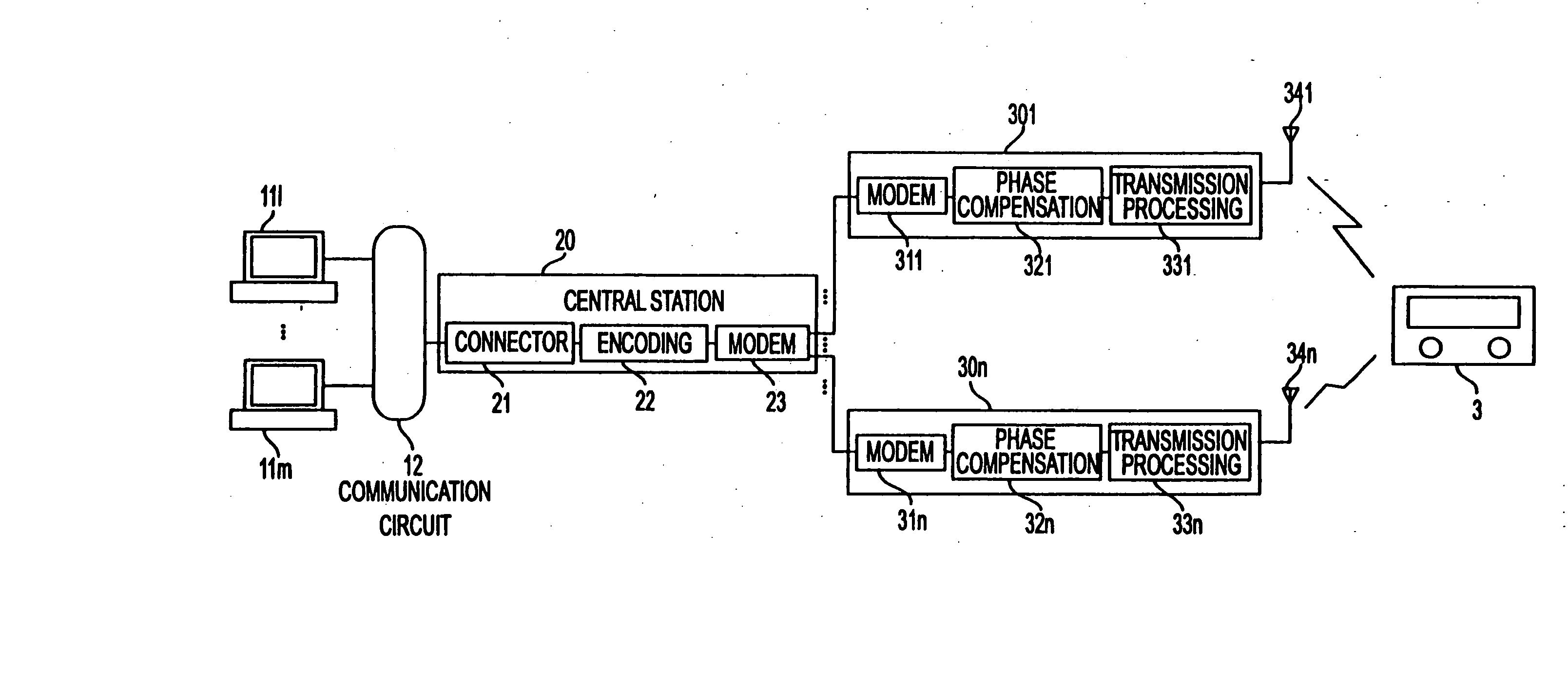
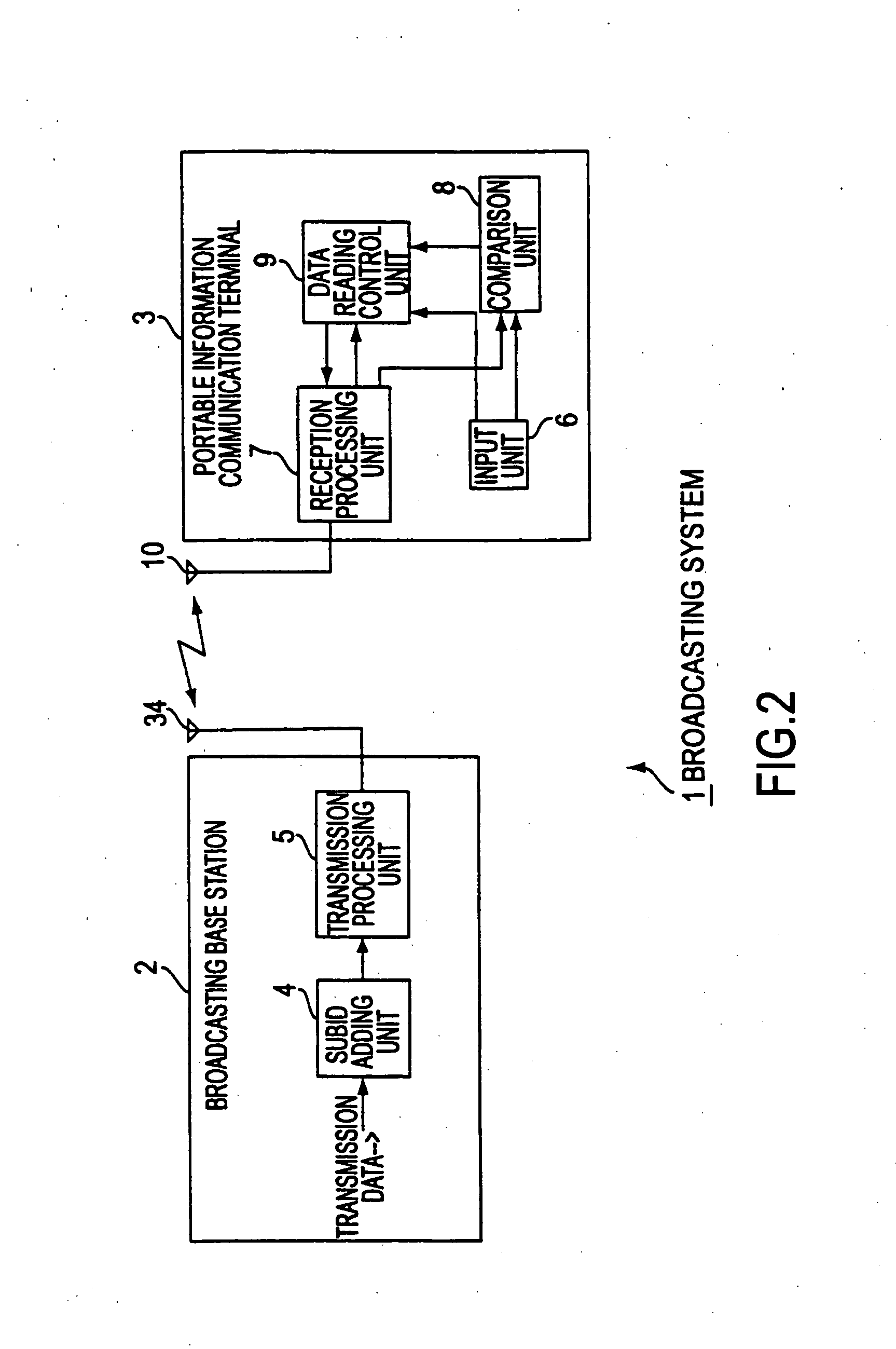
[0041] In the following, an embodiment of this invention is described in detail while making reference to the drawings. This embodiment is a broadcasting system in which data is transmitted wirelessly to a portable information communication terminal that comprises a data receiver.

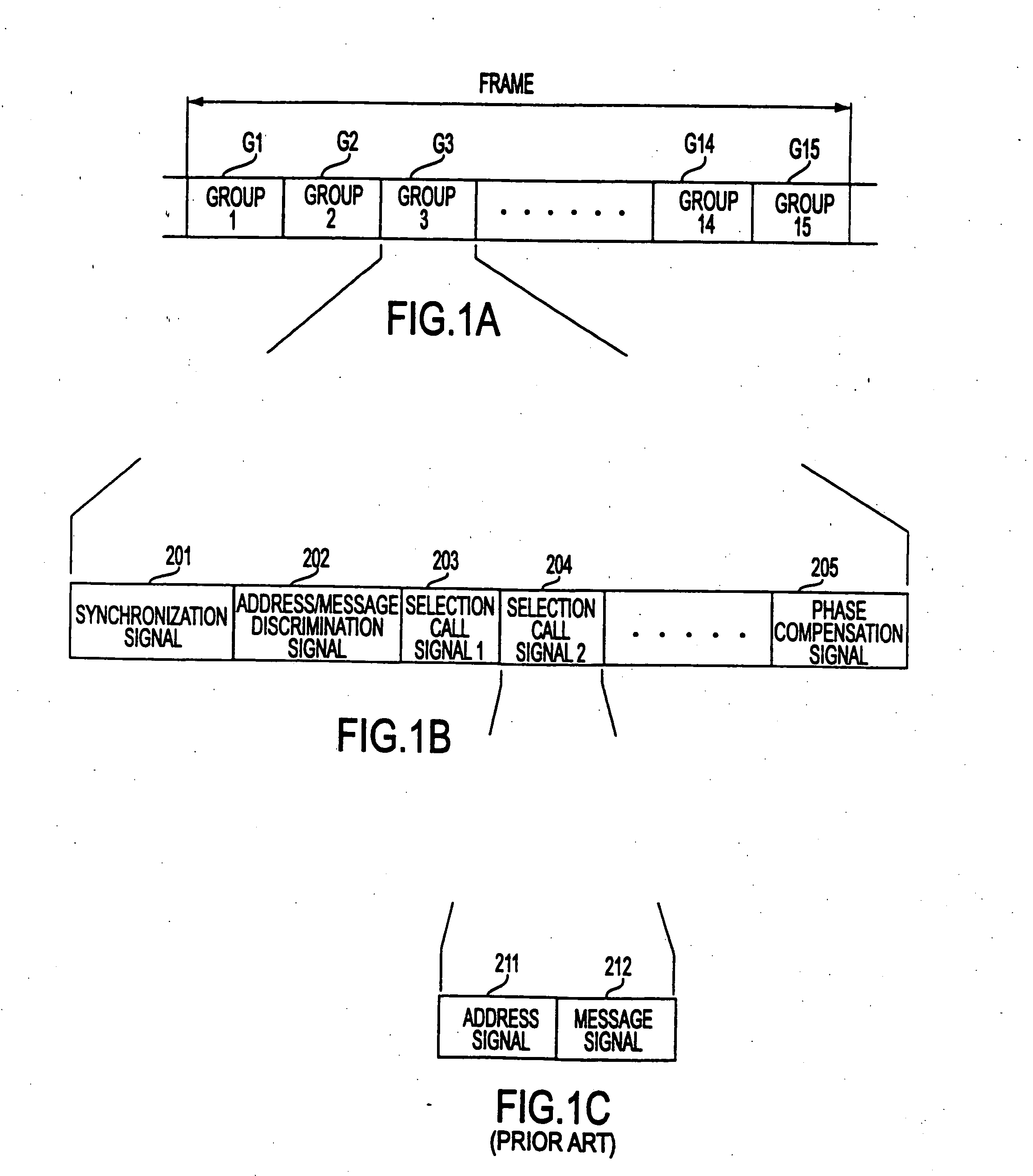
[0042] As shown in FIG. 2, a broadcasting system 1 includes a broadcasting base station 2, which broadcasts data of various types, and a portable information communication terminal 3, which receives and plays back data broadcast from broadcasting base station 2. In broadcasting system 1, transmission data, which is described below with reference to FIG. 3, is transmission-and reception-processed by prescribed data transmission cycles between broadcasting base station 2 and portable information communication terminal 3.

[0043] For example, the transmission data to be transmitted may be information that can be put to use by the user, such as information about public events or fashion information.

[0044] Broadca...


PUM


Abstract

A data transmission and reception system and method that make it possible to transmit and receive more types of information without changing the existing communication system include a broadcasting base station which has a subID adding unit, which arranges in the transmission data region the subIDs of the transmission data arranged in the transmission data region, and a transmission processing unit, which performs transmission processing on the transmission data as data transmission cycles. A portable information communication terminal has an input unit, which sets IDs and subIDs, a comparison unit, which has the address information comparison function of comparing the ID arranged in the selection call part and the ID set by the input unit and obtaining the result of the address information comparison, as well as the identification information comparison function of comparing the subID arranged in the transmission data region and the subID set by the input unit and obtaining the result of the identification address comparison, and a data reading unit, which performs reception control on the transmission data based on the address information comparison result and identification information comparison result obtained from the comparison unit.

Description

[0001] 1. Field of the Invention[0002] This invention concerns a data transmission method and data transmitter that transmits data to which address information has been added, a data receiver and data reception method that receives transmission data based on address information, and a data transmission and reception system that adds address information and transmits and receives data.[0003] 2. Description of Prior Art[0004] Wireless call systems or radio paging systems (merely referred as a radio paging system, hereinafter) that transmit information input by telephone have long been available. In a radio paging system, a so-called pager is used as an information reception terminal.[0005] In recent years, information broadcast services have become available in which various information is provided using this radio paging system. This information broadcast service makes it possible, for example, to receive on a pager or pager terminal various information such as information about publ...

Claims


Application Information

Patent Timeline
IPC IPC(8): H04M3/42H04B1/04H04B1/16H04B7/26H04H20/00H04H20/57H04H60/07H04H60/85H04J3/16H04M3/487H04W56/00H04W84/02H04W88/02H04W88/18
CPCH04W88/023H04W88/187H04B5/00
Inventor KAWAI, EIJIITO, TAKESHIYOSHIMORI, MASAHARU
Owner SONY COMPUTER ENTERTAINMENT INC
Learn More