Fuel injection device

a fuel injection device and fuel injection technology, applied in the direction of fuel injection apparatus, machine/engine, feed system, etc., can solve the problems of large number of parts, increased man-hour and installation cost, and easy disengagement of engaged parts

Inactive Publication Date: 2004-12-02
MITSUBISHI ELECTRIC CORP
View PDF6 Cites 29 Cited by
  • Summary
  • Abstract
  • Description
  • Claims
  • Application Information

AI Technical Summary

Problems solved by technology

Since the conventional fuel injection device used in an internal combustion engine is constructed as described above, the fuel injection device disclosed in the Japanese Patent Publication (unexamined) No. 1981-12051 has such problems that a large number of parts are necessary and man-hour and cost of installation are increased.
Since the fuel injection device disclosed in the Japanese Patent Publication (unexamined) No. 1991-31572 has a structure in which the snap springs extend in parallel to the axis of the fuel injection valves and are engaged with the engaging flan

Method used


Image

  • Fuel injection device
  • Fuel injection device
  • Fuel injection device

Examples


embodiment 1

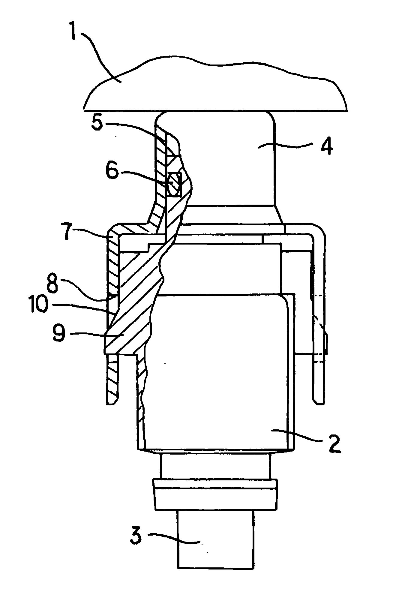
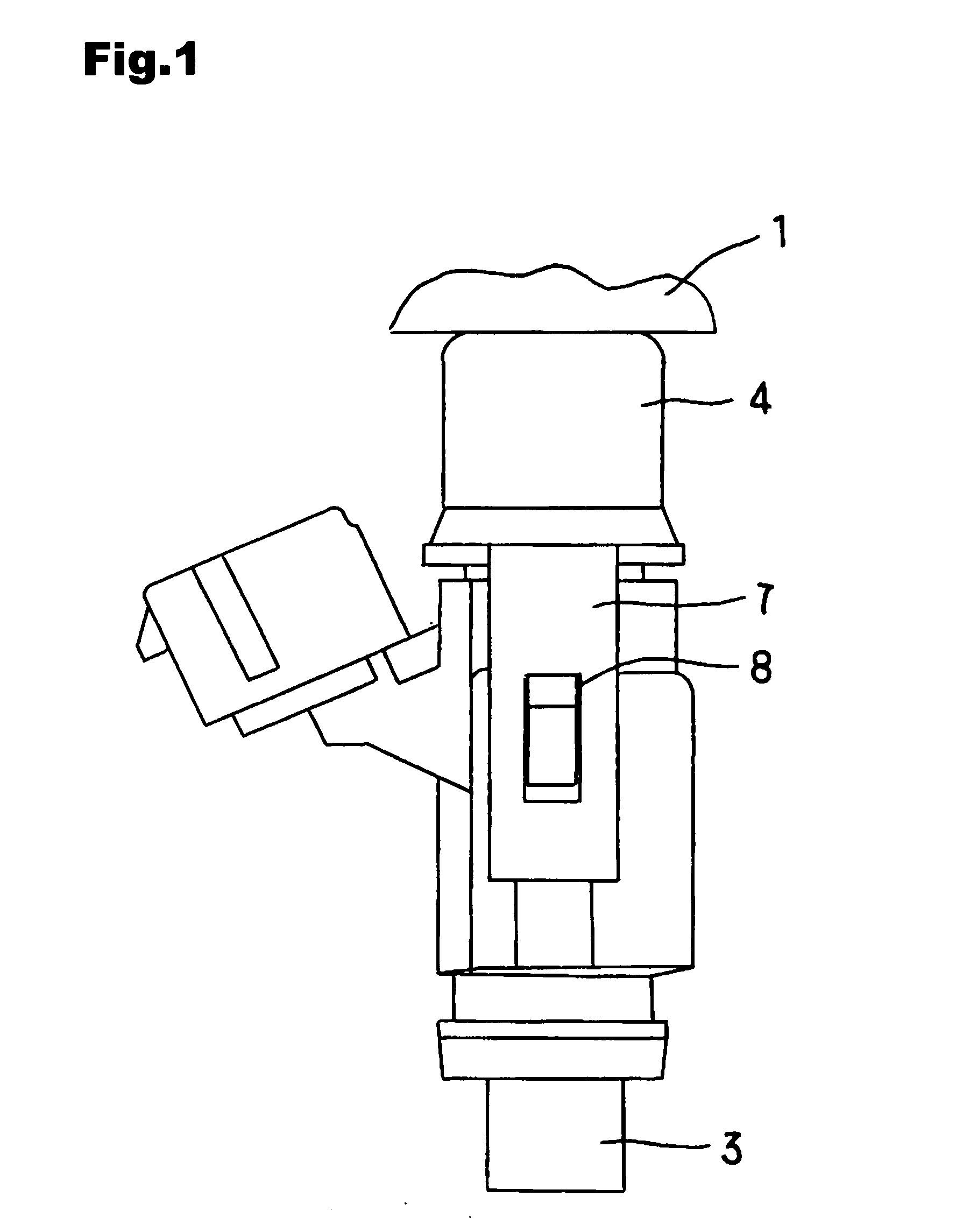
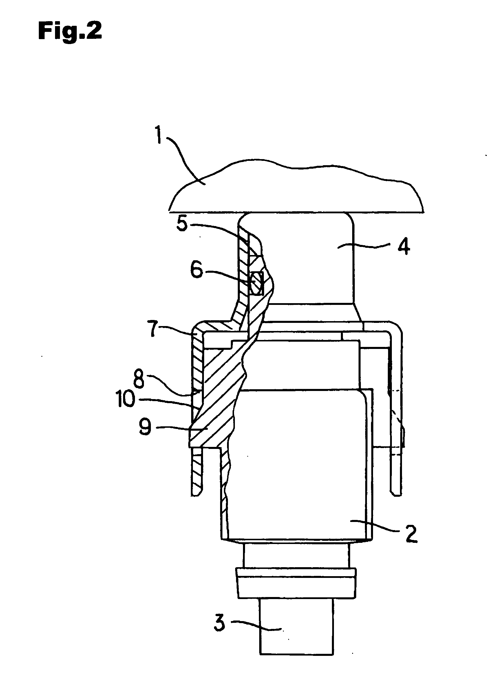
[0032] FIG. 1 is a front view showing a fuel injection device of the invention, FIG. 2 is a partially sectional side view of the fuel injection device, and FIG. 3 is a bird's-eye view showing a connecting pipe member.

[0033] In the drawings, a fuel supply system in this embodiment includes a fuel distribution pipe 1 and a fuel injection valve 2.

[0034] The fuel injection valve 2 is mounted on an intake pipe of an internal combustion engine not shown and injects fuel to an intake passage. A solenoid apparatus accommodated in the fuel injection valve causes a needle valve to act, in association with an armature, for opening and closing a fuel injection hole provided in a valve seat so that fuel is injected from a fuel-injecting portion 3.

[0035] The fuel distribution pipe 1 includes connecting pipe members 4 which distribute fuel to each cylinders of the internal combustion engine.

[0036] A fuel inflow port 5 of the fuel injection valve 2 is inserted in the connecting pipe member 4. An O...

embodiment 2

[0042] FIG. 4 is a front view showing a fuel injection device according to Embodiment 2 of the invention, FIG. 5 is a partially sectional side view of this fuel injection device, and FIG. 6 is a bird's-eye view showing a connecting pipe member.

[0043] Referring to the drawings, in order to hold the fuel injection valve 2, each connecting pipe member 4 is provided with a band-shaped protrusion 7 that protrudes from a free end part of the connecting pipe member 4 in the radial direction and further extends therefrom in the vertical direction, i.e., in the axial direction of the fuel injection valve 2.

[0044] This band-shaped protrusion 7 is provided with a fitting hole 8, and further this fitting hole 8 is provided with a protrusion 11 protruding inward.

[0045] Each fuel injection valve 2 is provided with a hollow 12 into which the protrusion 11 is fitted.

[0046] When the fuel inflow port 5 of the fuel injection vale 2 is inserted in the connecting pipe member 4, the fuel injection valve ...

embodiment 3

[0049] FIG. 7 is a front view showing a fuel injection device according to Embodiment 3 of the invention, FIG. 8 is a partially sectional side view of this fuel injection device, and FIG. 9 is a bird's-eye view showing a connecting pipe member.

[0050] In the drawings, in order to hold the fuel injection valve 2, each connecting pipe member 4 is provided with a band-shaped protrusion 7 that protrudes from a free end part of the connecting pipe member 4 in the radial direction and further extends therefrom in the vertical direction, i.e., in the axial direction of the fuel injection valve 2.

[0051] This band-shaped protrusion 7 is provided with a narrow portion 13 whose width is partially reduced. The band-shaped protrusion 7 is also provided with a fitting hole 8.

[0052] Each fuel injection valve 2 is provided with a protrusion 9.

[0053] When the fuel inflow port 5 of the fuel injection vale 2 is inserted in the connecting pipe member 4, the introduction slope 10 of the protrusion 9 move...


PUM


Abstract

Any specific member for fixation is omitted from a fuel injection device so that number of parts is reduced and the fuel injection device is constructed at a reasonable cost. The fuel injection device for use in an internal combustion engine is provided with a fuel distribution pipe 1, plural connecting pipe members 4, and plural fuel injection valves 2, and each of the fuel injection valves 2 is inserted into a connecting pipe member 4. A band-shaped protrusion 7 extends in the radial direction from a flange portion of the connecting pipe member 4 and further extends in parallel to the axis of the fuel injection valve 2. The band-shaped protrusion 7 is provided with a fitting hole 8, and each fuel injection valve 2 is provided with a protrusion 9 fitted into the fitting hole 8.

Description

[0001] 1. Field of the Invention[0002] The present invention relates to a fuel injection device used in an internal combustion engine and, more particularly, to mounting structure for mounting a fuel injection valve on a fuel distribution pipe.[0003] 2. Description of the Related Art[0004] As an example of conventional structure for mounting a fuel injection valve on a fuel distribution pipe, a fixing member that partially holds a connecting pipe member and the fuel injection valve and has a configuration corresponding to the fuel injection valve couples each of fuel injection valves with a fuel distributor without applying any force in the axial direction so as to fix the fuel injection valve in the axial direction (for example, see the Japanese Patent Publication (unexamined) No. 1981-12051 (FIGS. 1 and 2)).[0005] As another example of conventional structure for mounting a fuel injection valve on a fuel distribution pipe, a fuel injection valve is provided with at least two snap s...

Claims


Application Information

Patent Timeline
IPC IPC(8): F02M61/14F02M55/02
CPCF02M55/025F02M61/145F02M69/465F02M2200/16F02M2200/856
Inventor KONDO, TETSUJISUZUKI, MIKIHIKO
Owner MITSUBISHI ELECTRIC CORP
Why Eureka
Try Eureka