Radial force distributions in rock bits

a technology rock bits, which is applied in the field of radial force distribution in rock bits, can solve the problems of rock bits gyrating or laterally bouncing about the bottom hole, impacting the wall, and significant expense in the design and manufacture of drill bits, so as to reduce the efficiency of drill bit performance and reduce the life of drill bits

Inactive Publication Date: 2004-12-16
SMITH INT INC
View PDF16 Cites 43 Cited by
  • Summary
  • Abstract
  • Description
  • Claims
  • Application Information

AI Technical Summary

Benefits of technology

0032] As used herein, "radial forces" on the drill bit are the forces (or component of the forces) acting on the bit in a plane perpendicular to the bit axis. FIG. 8 shows one example of radial forces acting on a drill bit due to interference with a wall of a borehole. The drill bit 302, in the present example, is a roller cone drill bit having a cutting structure that includes three cones 302 A, 302 B, and 302 C. The earth formation 304 is fractured and sheared by the cutting elements (not shown) of the cone 302 A. Consequently, the shearing and fracturing of the earth formation 304 produces reaction forces in the vertical and radial directions. In particular, radial forces acting on a drill bit 302 tend to swing the drill bit 302 away from a borehole axis. For example, in FIG. 8, because of the radial force 306 (or reaction force 308) on cone 302 A, the drill bit 302 will swing away from the borehole axis 300 thereby causing a "swinging" or "whirl" effect about the borehole axis. This motion about the borehole axis is referred to as "bit whirl." Bit whirl may reduce the efficiency of a drill bit's performance with respect to the rate of penetration (ROP) and footage drilled by the drill bit. Further, bit whirl may damage cutting structure of the drill bit, leading to premature failure of the gage inserts and seals, and reduce the drill bit life. While bit whirl has been discussed above with respect to a roller cone drill bit, all bits can experience some sort of bit whirl. Furthermore, bit whirl during drilling does not only effect the drill bit, but can also have a detrimental effect on the BHA and the drill pipe of a drilling tool assembly.

Problems solved by technology

Significant expense is involved in the design and manufacture of drill bits.
However, roller cone bits are more complex than fixed cutter bits in that each roller cone independently rotates relative to the rotation of the bit body about axes oblique to the axis of the bit body.
Because each roller cone independently rotates about an axis oblique to the axis of the bit body, a conventional rock bit may experience unbalanced lateral forces (radial forces) that cause the rock bit to gyrate or laterally bounce about the bottom hole and impact the wall of the wellbore during drilling.
Bit whirling is an undesirable performance characteristic, because it results in inefficient drilling of the bottomhole and can potentially damage the bit prematurely.
Until recently, no reliable roller cone bit models had been developed which could take into consideration the location, orientation, size, height, and shape of each cutting element on the roller cone, and the interaction of each individual cutting element on the cones with earth formations during drilling.
However, methods have not been specifically developed for optimizing the performance of drill bits, particularly, roller cone bits, in drilling earth formations to analyze bit performance with respect to the lateral (radial) force of the bits.

Method used


Image

  • Radial force distributions in rock bits
  • Radial force distributions in rock bits
  • Radial force distributions in rock bits

Examples


Embodiment Construction

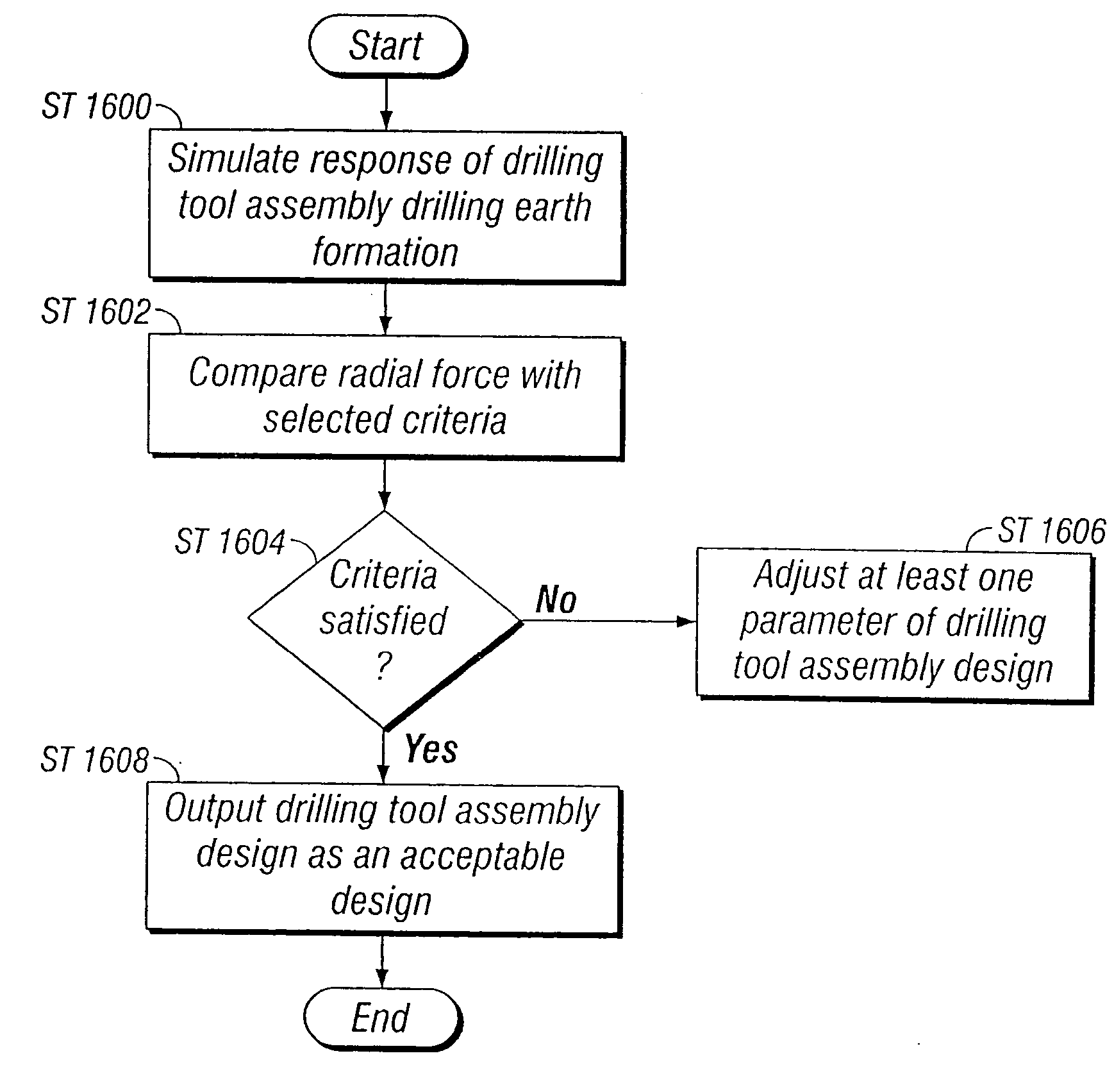
[0063] Another example of a method of designing a bit in accordance with an embodiment of the present invention will now be described with respect to FIGS. 9A-9C, 10A-10C, and 11A-11C. These figures show examples of resultant radial force output obtained from a simulation. The bit design is improved through several iterations, in accordance with the present invention. In this example, a simulation as described in U.S. Pat. No. 6,516,293, issued on [INSERT Date.] entitled, "Methods for Simulating Drilling of Roller Cone Bits and its Application to Roller Cone Bit Design and Performance" is used to obtain resultant radial forces as briefly described below with reference to FIG. 12.

[0064] Initially, parameters for the simulation are selected (Step 1200), which define the initial bit design, and the simulation begins by rotating the defined bit (Step 1202) to determine a new location of the cutting elements located on the bit (Step 1204). Interferences between the cutting elements and t...


PUM


Abstract

A method for designing a drill bit in an earth formation, including defining parameters for a simulation of the drill bit drilling in earth formation, where the parameters comprise at least bit design parameters; executing the defined simulation; obtaining radial forces resulting from the executing of the defined simulation; applying a criterion to the obtained radial forces; and adjusting one of the at least bit design parameters in response to the applying of the criteria.

Description

[0001] This is an utility application, which claims priority to U.S. Provisional Application No. 60 / 458,075, filed on Mar. 26, 2003.BACKGROUND OF INVENTION[0002] Roller cone rock drill bits and fixed cutter drill bits are commonly used in the oil and gas industry for drilling wells. FIG. 1 shows one example of a conventional drilling system drilling an earth formation. The drilling system includes a drilling rig 10 used to turn a drill string 12 which extends downward into a well bore 14. Connected to the end of the drill string 12 is a bottomhole assembly, which includes at least a drill bit 20 that cuts through and breaks up earth formation as it is rotated.[0003] One example of a roller cone-type drill bit is shown in FIG. 2. Roller cone bits 20 typically comprise a bit body 22 having an externally threaded connection at one end 24, and a plurality of roller cones 26 (usually three as shown) attached to the other end of the bit and able to rotate with respect to the bit body 22. ...

Claims


Application Information

Patent Timeline
Patent Type & Authority Applications(United States)
IPC IPC(8): E21B10/00E21B10/08G06F17/50G06F19/00
CPCE21B10/00
Inventor CENTALA, PRABHAKARAN K.BOUDRARE, MOHAMMEDHUANG, SUJIAN
Owner SMITH INT INC
Why Eureka
Try Eureka