Biometric padlock

Inactive Publication Date: 2004-12-23
SUN CONRAD +1
View PDF18 Cites 66 Cited by
  • Summary
  • Abstract
  • Description
  • Claims
  • Application Information

AI Technical Summary

Problems solved by technology

However, in the past the cost of fingerprint readers has limited fingerprint recognition to use with or in applications involving relatively expensive devices; i.e., guns, vehicles, etc. costing thousands of dollars.
Unfortunately, not all applications that would benefit from fingerprint recognition involve such costly equipment.
Nevertheless, it remains difficult to justify use of a fingerprint recognition system that is more costly by an order of magnitude than the rest of the equipment with which the reader is used.
There are still however, some applications that have not yet been implemented because at first blush they do not appear to be justified economically and they do not appear to be feasible in terms of size constraints.
1. Unlock--to open the device one pushes the U Button momentarily which wakes up the lock (applies power) and activates the sensor and electronics. The U button is positioned near the sensor to be automatically depressed prior to passing the finger over the sensor. The finger is passed over the sensor and within 1-2 seconds a solenoid in the lock releases the spring-loaded shackle, which then pops up.
2. Program--The

Method used


Image

  • Biometric padlock
  • Biometric padlock
  • Biometric padlock

Examples


Embodiment Construction

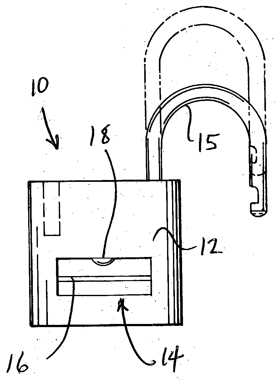
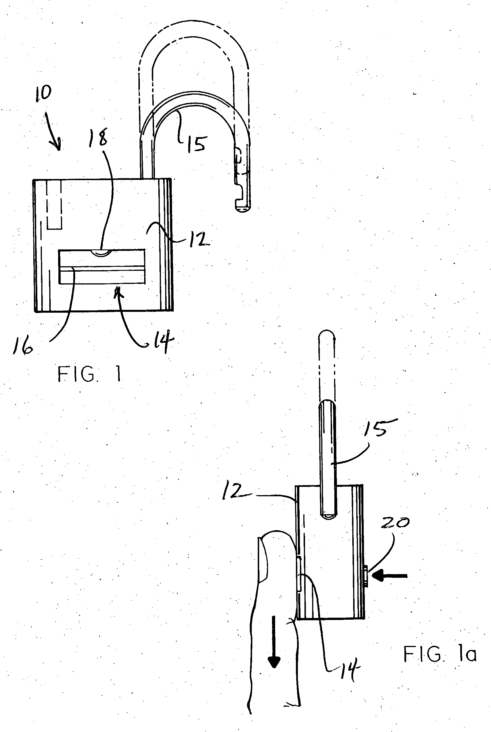
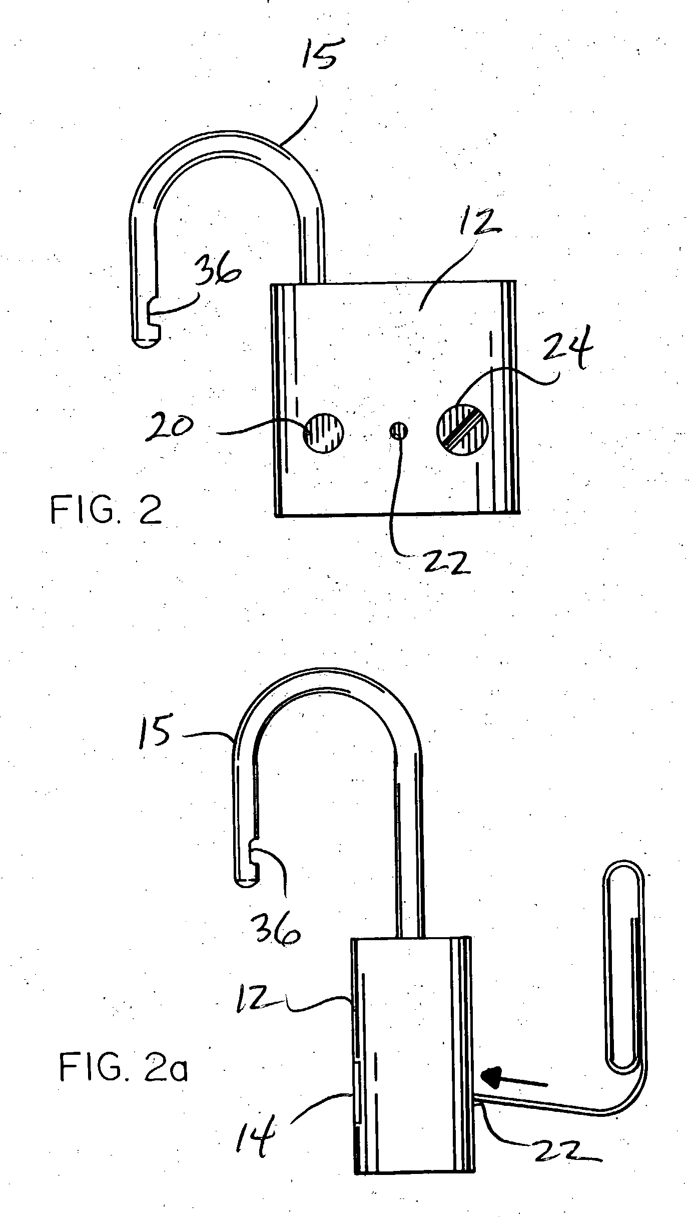
[0023] Referring to the accompanying drawings, it will be seen that a padlock 10 comprises a body 12, a locking arm or shackle 15, a biometric member 14, the latter comprising a "U" button 18, a line sensor or reader 16, a "P" button 20, a reset button 22, a battery access 24, a printed circuit board (PCB) 26, a sensor board 28, a solenoid 30, a magnetic pole 32, a locking pin 34, a spring 35 and a shackle recess 36.

[0024] The body 12 is of conventional size and shape as compared to key lock or combination lock padlocks. Similarly, locking arm or shackle 15 is of a typical shape and size as compared to ordinary padlocks. However, unlike a conventional padlock, as shown in FIG. 1 and FIG. 1a padlock 10 comprises a biometric member having an unlock activation ("U") button 18 and a fingerprint reader line sensor 16 on one side of the body 12 and as shown in FIG. 2 and FIG. 2a, a programming activation ("P") button 20 and reset switch 22 on the opposite side of the body 12. Also include...


PUM


Abstract

A padlock having a body and a shoekle comprises a fingerprint sensor, a fingerprint data memory device and an electromagnetic device activated by a sensed and matched fingerprint to unlock the shackle from the body. Unlock and programming buttons respectively activate the sensor and configure the data memory device to receive new fingerprint data of those authorized to unlock the padlock.

Description

[0001] 1. Field of the Invention[0002] The present invention relates generally to padlocks and more specifically to a biometric padlock which, in a preferred embodiment, functions as an electro-mechanical device utilizing fingerprint recognition to open the lock.[0003] 2. Background Art[0004] Advances in the technology of fingerprint recognition have made it feasible to employ such technology to limit access to certain equipment to selected individuals. By way of example, U.S. Pat. Nos. 4,467,545 and 5,812,252 relate to the use of fingerprint recognition to activate a fire arm only for individuals who's fingerprint patterns have been previously stored. Similarly, U.S. Pat. Nos. 6,078,265 and 6,100,811 relate to fingerprint recognition for use in vehicles to limit access to vehicle operation to individuals who's fingerprint patterns have been previously stored. However, in the past the cost of fingerprint readers has limited fingerprint recognition to use with or in applications invo...

Claims


Application Information

Patent Timeline
IPC IPC(8): E05B47/06E05B67/22G07C9/00
CPCE05B47/0002E05B47/06E05B67/22G07C9/00563Y10T70/459
Inventor SUN, CONRADSCHWARTZ, JOHN
Owner SUN CONRAD
Why Eureka
Try Eureka