Method for forming of tubular work-pieces using a segmented tool

a segmented tool and workpiece technology, applied in the direction of shaping tools, manufacturing tools, metal-working apparatuses, etc., can solve the problems of high cost of base blocks, significant problems in hydroforming of large workpieces, etc., and achieve the effect of preventing the use of very large tooling blocks

Inactive Publication Date: 2004-12-23
SAPA PROFILBOCKNING
View PDF4 Cites 4 Cited by
  • Summary
  • Abstract
  • Description
  • Claims
  • Application Information

AI Technical Summary

Benefits of technology

0006] An object of the present invention is to provide a simplified tool for hydroforming of tubular work-pieces, where the use of

Problems solved by technology

Hydroforming of large work-pieces, such as sidemembers for car body structures presents significant problems due to the difficulty of handling the very heavy tools that are required as moulds during forming.
The disadvantage of this arrangement is the high cost for the base blocks and the fact that these base blocks are even heavier and more d

Method used


Image

  • Method for forming of tubular work-pieces using a segmented tool
  • Method for forming of tubular work-pieces using a segmented tool

Examples


example 2

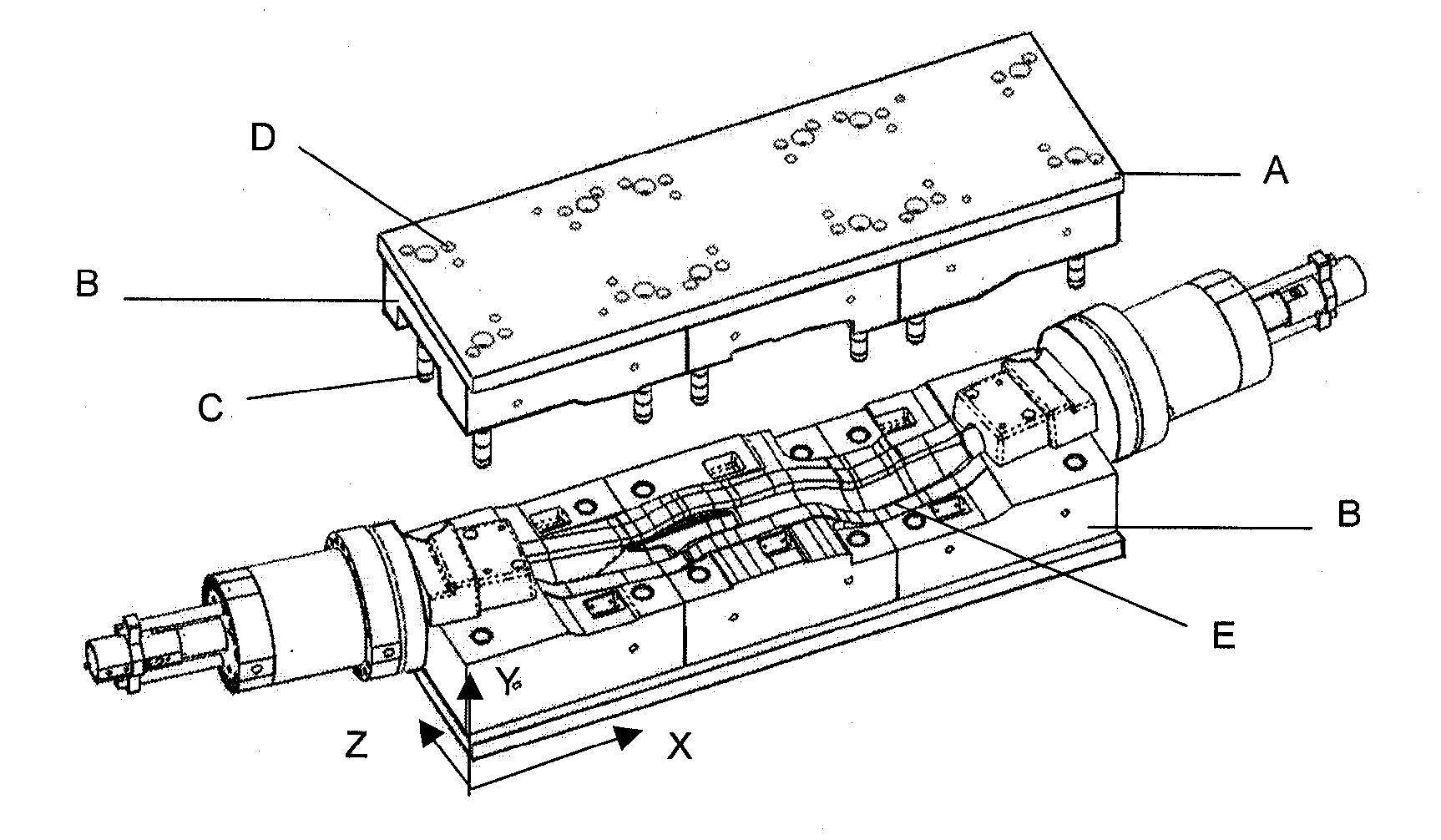
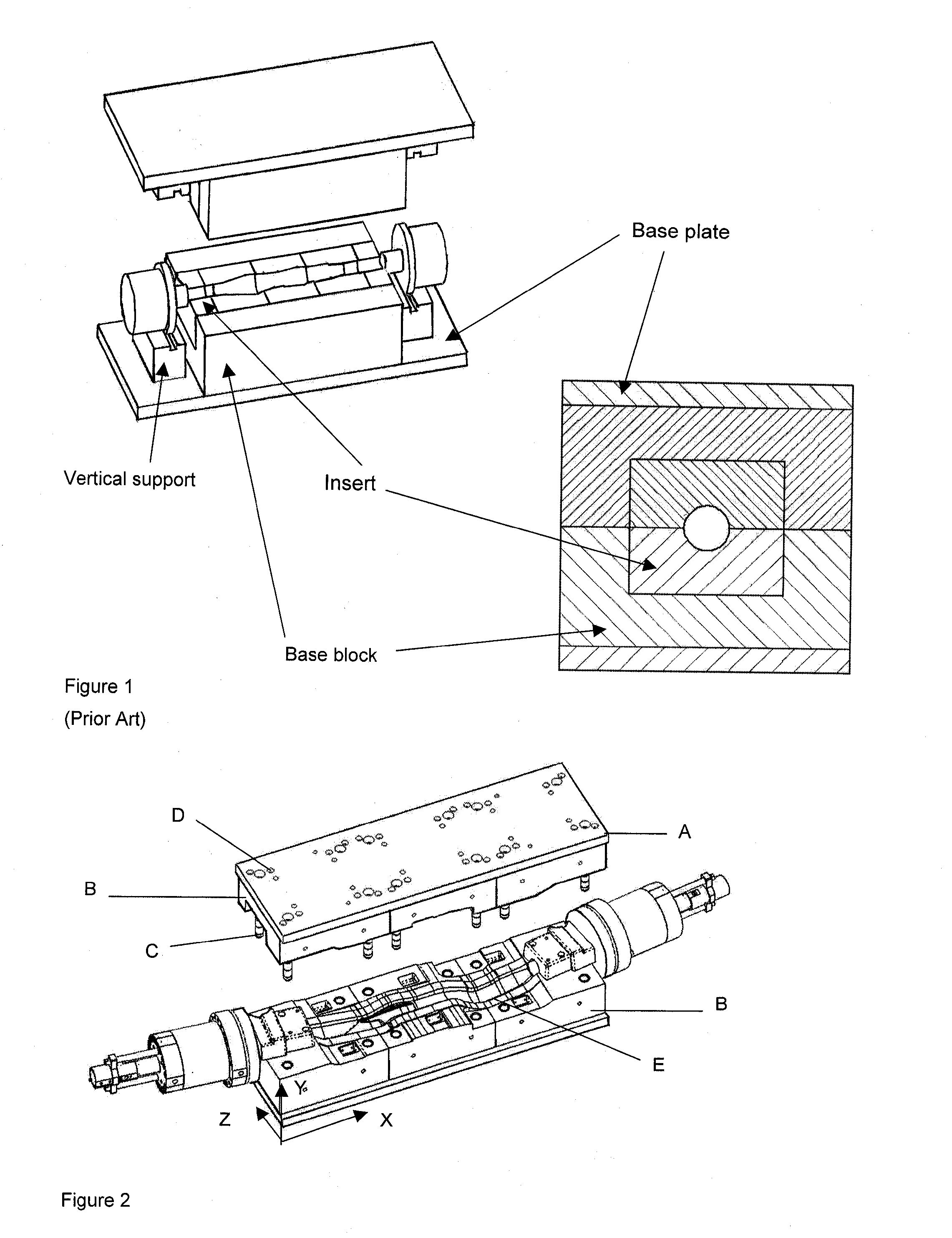
[0028] A hydroforming tool as in example 1, but without retaining elements, is used for forming a tubular work-piece made from extruded aluminium. The tubular work-piece is put in said cavity and the upper and lower tool inserts are moved together to deform portions of the work-piece while supplying work-piece material axially inwardly. Pressure of 1500 tonnes is applied to the tool parts by the tool punch. Pressure is then applied to the inside of the work-piece by increasing the pressure on said liquid to 1000 bar. The tool is opened and the formed pieces are removed. No movement of the segments could be observed.


PUM

PropertyMeasurementUnit
Forceaaaaaaaaaa
Shapeaaaaaaaaaa

Abstract

The hydroforming tool of the present invention comprises a pair of upper and lower tool inserts (B) having open axial ends and defining an elongated cavity there between when said tool inserts are forced together. The upper and/or lower tool inserts are composed of segments that are attached to the upper and a lower base plates, (A), by bolts. Retaining elements, such as pins, are introduced into holes in the base plates and continues into cavities (D) formed in the segmented inserts. This prevents the insert segments from moving during the forming operation. In this way the use of base blocks may be omitted. Sometimes the friction force acting between the base plate and segmented inserts, caused by the high pressure applied to the tool surfaces, is sufficient to prevent the separation of the segments, whereby the segments are kept in place without the use of retaining elements.

Description

[0001] This application claims the benefit of a U.S. Provisional Application No. 60 / 481,308, filed on Aug. 29, 2003.BACKGROUND OF INVENTION[0002] The invention relates to the forming of tubular workpieces by internal pressure created by a fluid, i e hydroforming, and in particular to a segmented tool used for said forming operation.[0003] The hydroforming process is described in "Hydroforming--Umformen mit Wirkmedien im Automobilbau, Verlag Moderne Industrie, Landsberg, 2002". In this process tubes formed to final shape by insertion in a tool where the tubes are expanded by applying an internal pressure to the inside of the tube using a fluid. The tubes may be straight or pre-bent depending on the final requirements.[0004] Hydroforming of large work-pieces, such as sidemembers for car body structures presents significant problems due to the difficulty of handling the very heavy tools that are required as moulds during forming. For this reason segmented tool inserts, i e tools that c...

Claims


Application Information

Patent Timeline
IPC IPC(8): B21D26/02
CPCB21D26/047B21D37/02
Inventor BJUHR, JONASNILSSON, TOMAS
Owner SAPA PROFILBOCKNING
Why Eureka
Try Eureka