Magnetic resonance imaging interference immune device
What is AI technical title?
AI technical title is built by PatSnap AI team. It summarizes the technical point description of the patent document.
a technology of magnetic resonance imaging and immune device, which is applied in the direction of magnetic variable regulation, instruments, etc., can solve the problems of harmful tissue stimulation, damage to electronics, and often presents problems, and achieve the effect of reducing the effect of induced voltage on the device and reducing the effect of induced voltag
Inactive Publication Date: 2004-12-30
MEDTRONIC INC
View PDF17 Cites 96 Cited by
Summary
Abstract
Description
Claims
Application Information
AI Technical Summary
This helps you quickly interpret patents by identifying the three key elements:
Problems solved by technology
Method used
Benefits of technology
Benefits of technology
0026] A first aspect of the present invention is a voltage compensation unit for reducing the effects of induced voltages upon a device to a safe level. The voltage compensation unit includes a sensing circuit to sense voltages induced in conductive components of the device, the voltages being induced by changing magnetic fields and a compensation circuit, operatively connected to the sensing circuit and responsive thereto, to provide opposing voltages to the device to reduce the effects of induced voltages caused by changing magnetic fields.
Problems solved by technology
1. Erroneous signals to be induced / generated in a sensing lead or device or circuit;
2. Damage to electronics; and / or
3. Harmful stimulation of tissue, e.g. heart muscle, nerves, etc.
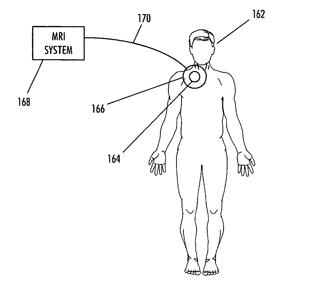
As noted above, the use of the MRI process with patients who have implanted medical assist devices; such as cardiac assist devices or implanted insulin pumps; often presents problems.
Since the sensing systems and conductive elements of these implantable devices are responsive to changes in local electromagnetic fields, the implanted devices are vulnerable to external sources of severe electromagnetic noise, and in particular, to electromagnetic fields emitted during the magnetic resonance imaging (MRI) procedure.
A common implantable pacemaker can, under some circumstances, be susceptible to electrical interference such that the desired functionality of the pacemaker is impaired.
Such electrical interference can damage the circuitry of the cardiac assist systems or cause interference in the proper operation or functionality of the cardiac assist systems.
For example, damage may occur due to high voltages or excessive currents introduced into the cardiac assist system.
Moreover, problems are realized when the placement of the implant is next to particular organs.
This induced voltage (current) can stimulate the heart inappropriately and can cause heart damage or death.
Method used
Image
Click on the blue label to locate the original text in one second.
Reading with bidirectional positioning of images and text.
Examples
Embodiment Construction
[0078] The present invention will be described in connection with preferred embodiments; however, it will be understood that there is no intent to limit the present invention to the embodiments described herein. On the contrary, the intent is to cover all alternatives, modifications, and equivalents as may be included within the spirit and scope of the present invention as defined by the appended claims.
[0079] For a general understanding of the present invention, reference is made to the drawings. In the drawings, like reference have been used throughout to designate identical or equivalent elements. It is also noted that the various drawings illustrating the present invention are not drawn to scale and that certain regions have been purposely drawn disproportionately so that the features and concepts of the present invention could be properly illustrated.
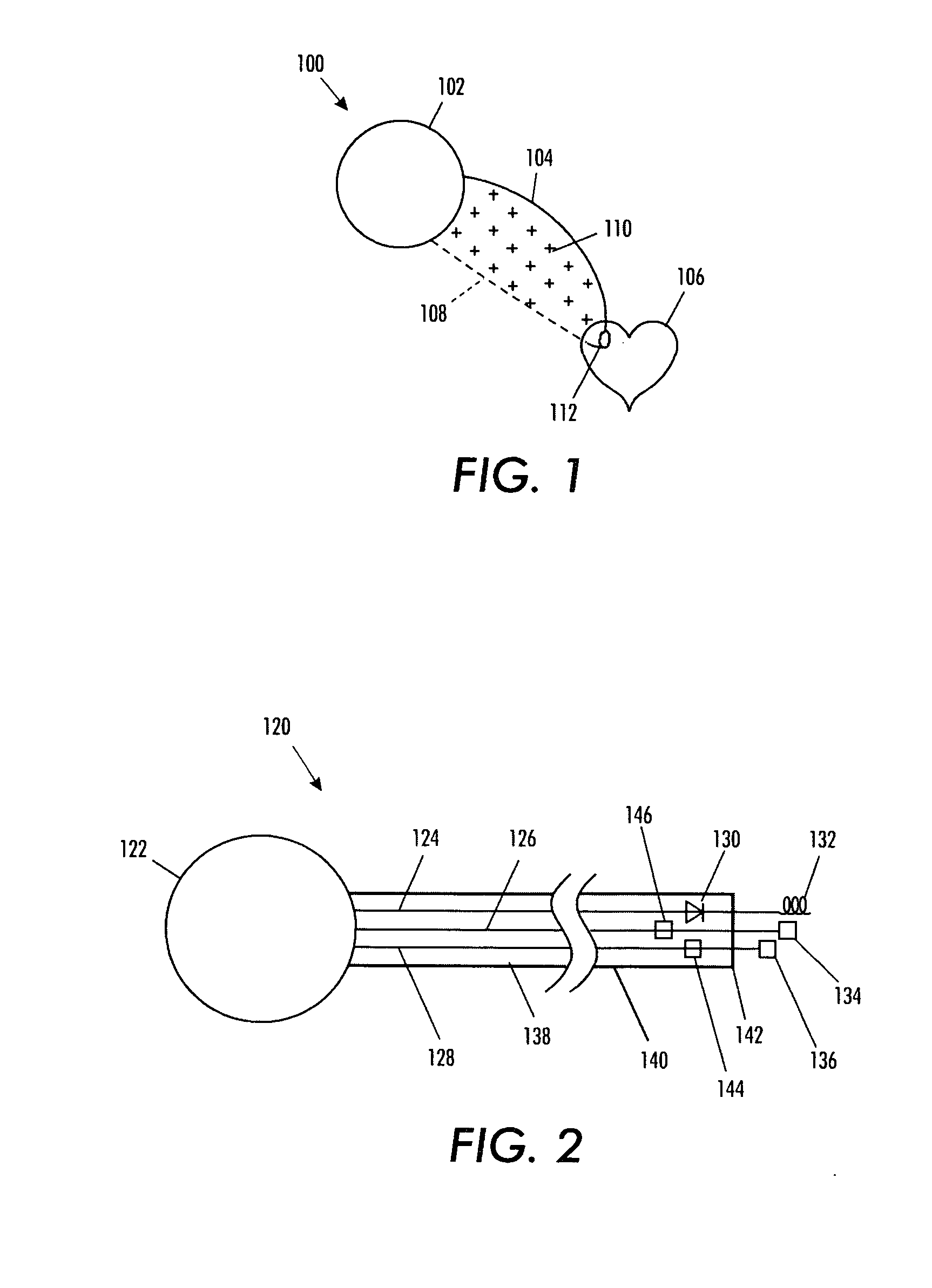
[0080] FIG. 1 is a schematic showing a typical pacemaker arrangement 100. The pacemaker comprises a pulse generator canister 102 ...
PUM
Abstract
A voltage compensation unit reduces the effects of induced voltages upon a device having a single wire line. The single wire line has balanced characteristic impedance. The voltage compensation unit includes a tunable compensation circuit connected to the wire line. The tunable compensation circuit applies supplemental impedance to the wire line. The supplemental impedance causes the characteristic impedance of the wire line to become unbalanced, thereby reducing the effects of induced voltages caused by changing magnetic fields.
Description
CROSS-REFERENCE TO RELATED US PATENT APPLICATIONS[0001] This application is a continuation-in-part of U.S. patent application Ser. No. 10 / 780,261, filed on Feb. 17, 2004, which application (U.S. patent application Ser. No. 10 / 780,261) claims priority under 35 U.S.C. .sctn.119(e) from U.S. Provisional Patent Application Ser. No. 60 / 482,177, filed on Jun. 24, 2003. The entire contents of U.S. Provisional Patent Application Ser. No. 60 / 482,177 and U.S. patent application Ser. No. 10 / 780,261 are hereby incorporated by reference.PRIORITY INFORMATION[0002] This application claims priority under 35 U.S.C. .sctn.119(e), through U.S. patent application Ser. No. 10 / 780,261, filed on Feb. 17, 2004, to U.S. Provisional Patent Application Ser. No. 60 / 482,177, which was filed on Jun. 24, 2003.CROSS REFERENCE TO RELATED PATENT APPLICATIONS[0003] The subject matter of co-pending U.S. patent application Ser. No. 09 / 885,867, filed on Jun. 20, 2001, entitled "Controllable, Wearable MRI-Compatible Card...
Claims
Application Information
Patent Timeline
Application Date:The date an application was filed.
Publication Date:The date a patent or application was officially published.
First Publication Date:The earliest publication date of a patent with the same application number.
Issue Date:Publication date of the patent grant document.
PCT Entry Date:The Entry date of PCT National Phase.
Estimated Expiry Date:The statutory expiry date of a patent right according to the Patent Law, and it is the longest term of protection that the patent right can achieve without the termination of the patent right due to other reasons(Term extension factor has been taken into account ).
Invalid Date:Actual expiry date is based on effective date or publication date of legal transaction data of invalid patent.
Patent Type & AuthorityApplications(United States)

