Calibration apparatus for smart antenna and method thereof

a technology of smart antennas and calibration apparatuses, applied in electrical apparatus, substation equipment, antennas, etc., can solve the problems of complicated process, limited implementation of the method proposed in the articles 1 and 2 and the difficulty of providing the ideal beam of the smart antenna system

Inactive Publication Date: 2004-12-30
CHOI SEUNG WON
View PDF4 Cites 21 Cited by
  • Summary
  • Abstract
  • Description
  • Claims
  • Application Information

AI Technical Summary

Problems solved by technology

However, in the receiving mode, the ideal beam of the smart antenna system is hard to be provided due to various technical difficulties.
However, the method proposed in the article 1 and 2 has implement limitations.
The additional element for calibration has to be located in a center of the circu

Method used


Image

  • Calibration apparatus for smart antenna and method thereof
  • Calibration apparatus for smart antenna and method thereof
  • Calibration apparatus for smart antenna and method thereof

Examples


Embodiment Construction

[0033] Other objects and aspects of the invention will become apparent from the following description of the embodiments with reference to the accompanying drawings, which is set forth hereinafter.

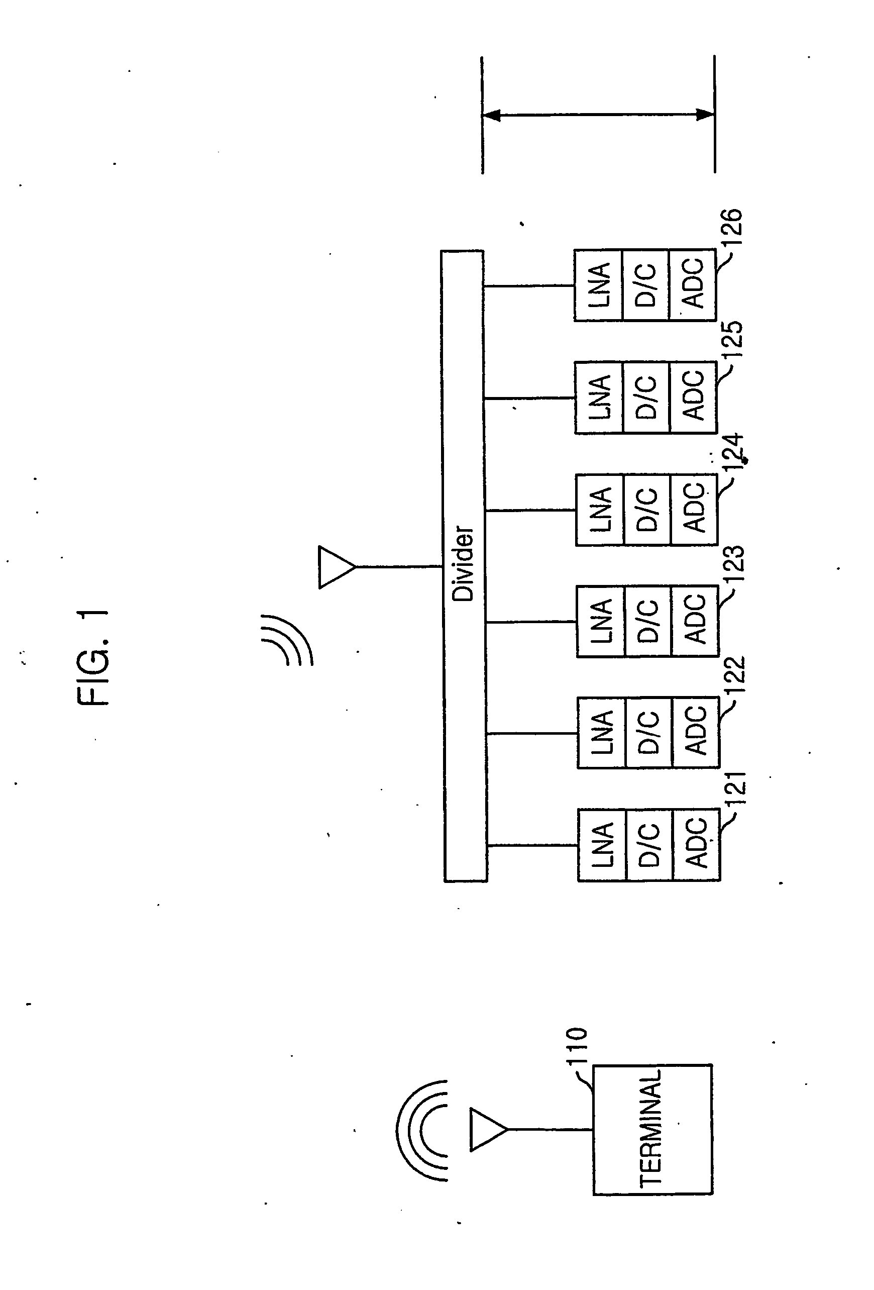
[0034] FIG. 1 is a diagram for explaining necessity of calibration in a wireless communication system in accordance with a preferred embodiment of the present invention.

[0035] As shown in FIG. 1, an array antenna system, in which the present invention is implemented, receives signals transmitted from a mobile station 110, divides the received signals to a receiving circuit of each antenna element of the array antenna by using a divider and measures phase error of each antenna element.

[0036] FIG. 1 shows an example of measuring the phase error of six antenna elements by using a value of an element of antenna 212 as a standard value for comparison the phase error.

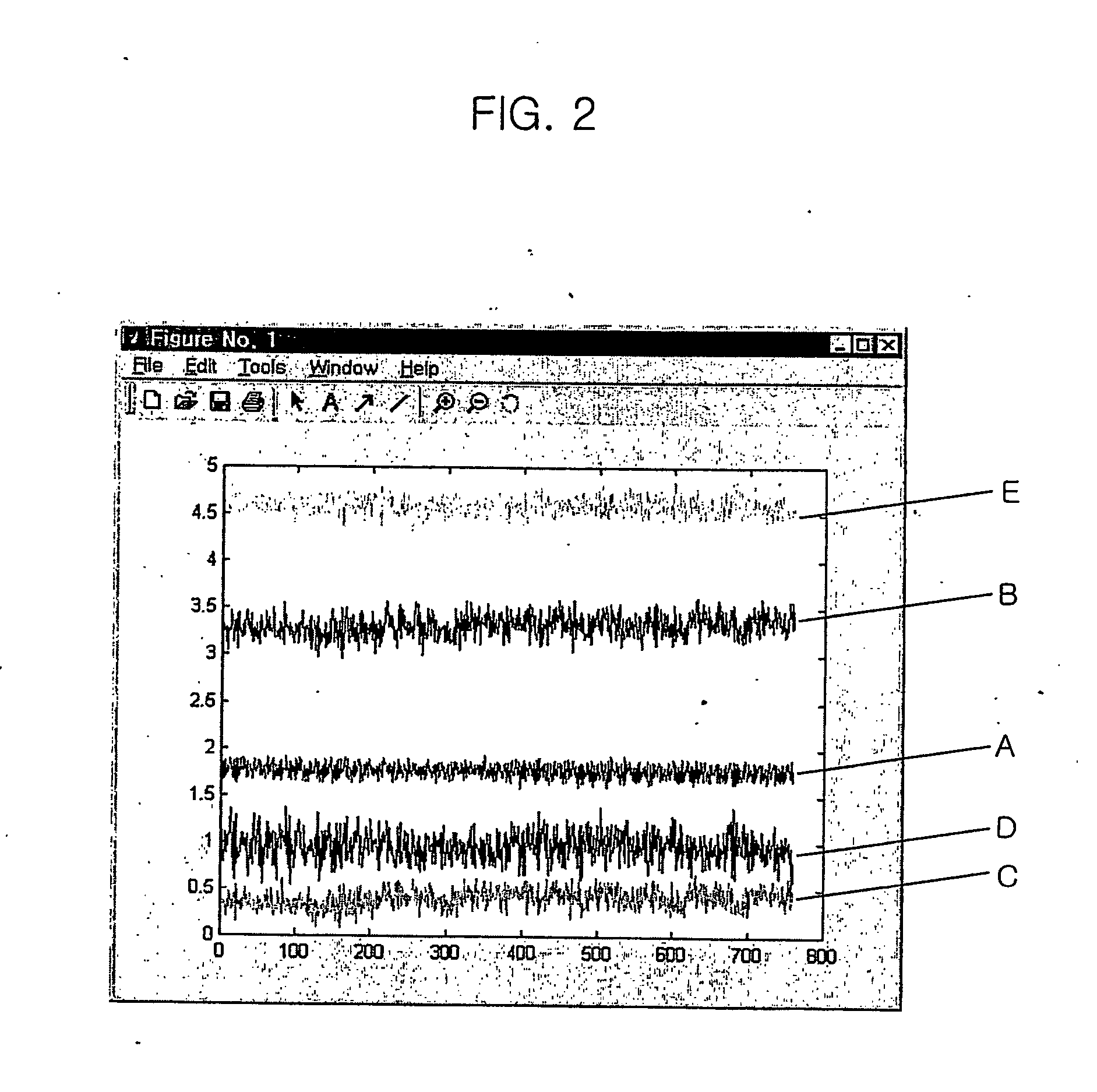
[0037] Table.1 shows mean values of the phase error of five antenna elements 122 to 126 by using the first antenna element 121 as ...


PUM


Abstract

A calibration apparatus for smart antenna and a method thereof are disclosed. The calibration apparatus in a receiving mode of an array antenna system includes: an additional antenna for receiving a calibration signal, which is used for calibration, from one of transmitting antennas; a frequency converter for converting a frequency of the calibration signal received from the additional antenna and generating a frequency-converted signal; a plurality of receiving frequency-converted signal from the frequency converter and outputting the frequency-converted signal; a plurality of receiving modules for converting the frequency-converted signal from the receiving antenna to have characteristics for the array antenna system; a transmitting module for generating the calibration signal and providing the calibration signal to the transmitting antenna; a calibration unit for controlling each of the receiving antennas, the receiving modules, the transmitting antenna and the transmitting modules to have the same phase characteristics based on signals received from the receiving modules; and a plurality of switches for switching a connection between the frequency converter and the receiving antennas.

Description

[0001] The present invention relates to a calibration apparatus and method for an array antenna and a computer readable record medium for executing the method and, more particularly, to the calibration apparatus and method of the array antenna for revising a phase characteristics of a receiver and transmitter coupled to each antenna element in the wireless communication environment.BACKGROUND ARTS[0002] In generally, a smart antenna system controls a direction of the antenna automatically toward an optimized direction in response to information analyzed from received input signals of each element of an antenna array. Such the smart antenna is called as an adaptive array antenna.[0003] An object of the smart antenna system is to provide an ideal beam, which gives the maximum gain to a direction of a mobile station and the minimum gain to an undesired direction by using a parameter value calculated from received signals in every snapshot. The ideal beam of the smart antenna system has...

Claims


Application Information

Patent Timeline
IPC IPC(8): H01Q21/00H01Q3/26
CPCH01Q3/267H01Q21/00
Inventor CHOI, SEUNG-WON
Owner CHOI SEUNG WON
Why Eureka
Try Eureka