Camping tent with improved ventilation

Inactive Publication Date: 2005-01-06
APPL DES GAZ AG
View PDF11 Cites 15 Cited by
  • Summary
  • Abstract
  • Description
  • Claims
  • Application Information

AI Technical Summary

Benefits of technology

Since the lower border of the outer wall can be raised it is possible to create a chimney effect inside the ten

Problems solved by technology

As a consequence, the exchange of air between the interior and exterior of the tent is extremely limited.
The temperature can therefore rise to quite uncomfortable levels for the occupants of the tent.
A large am

Method used


Image

  • Camping tent with improved ventilation
  • Camping tent with improved ventilation
  • Camping tent with improved ventilation

Examples


Embodiment Construction

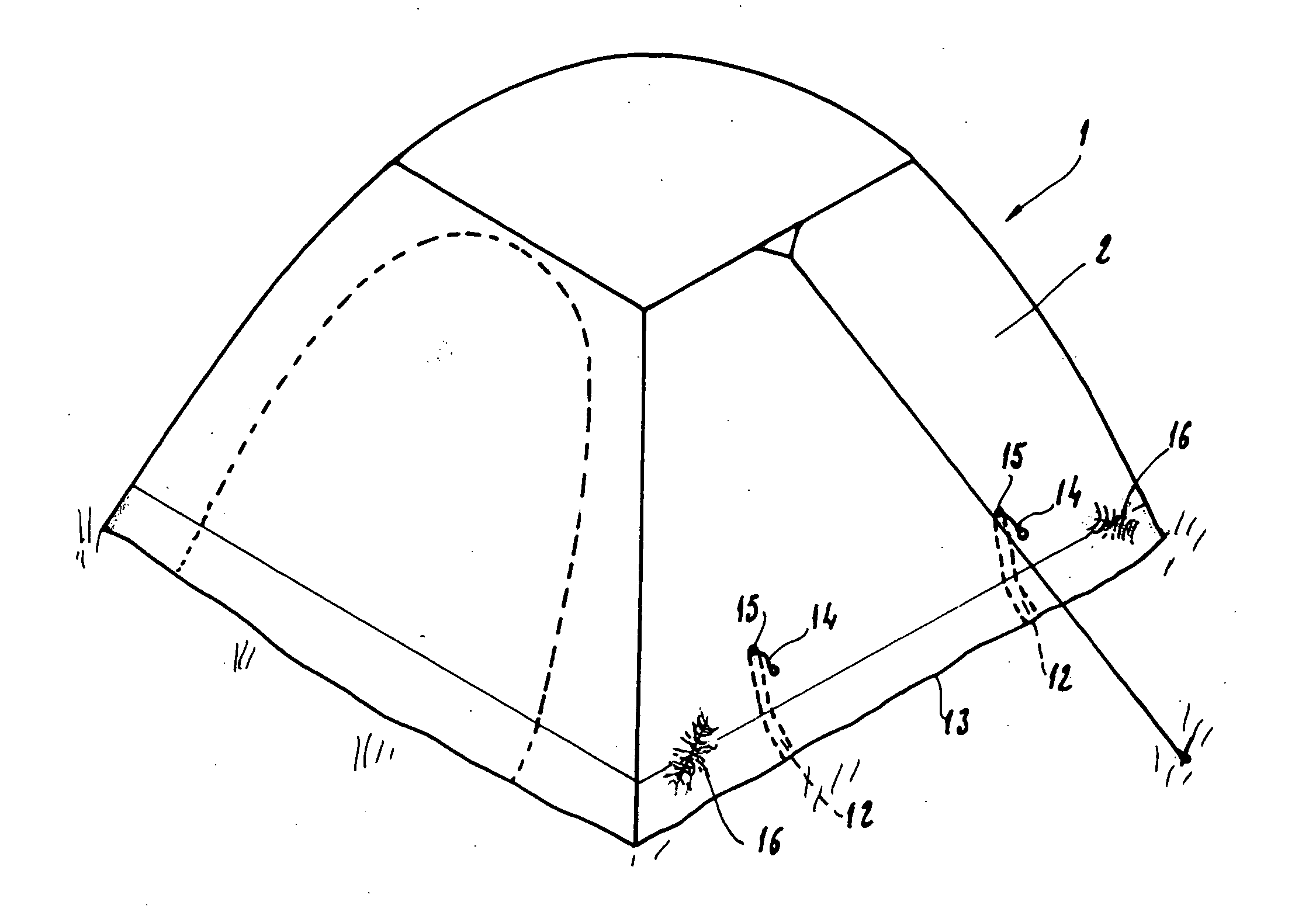
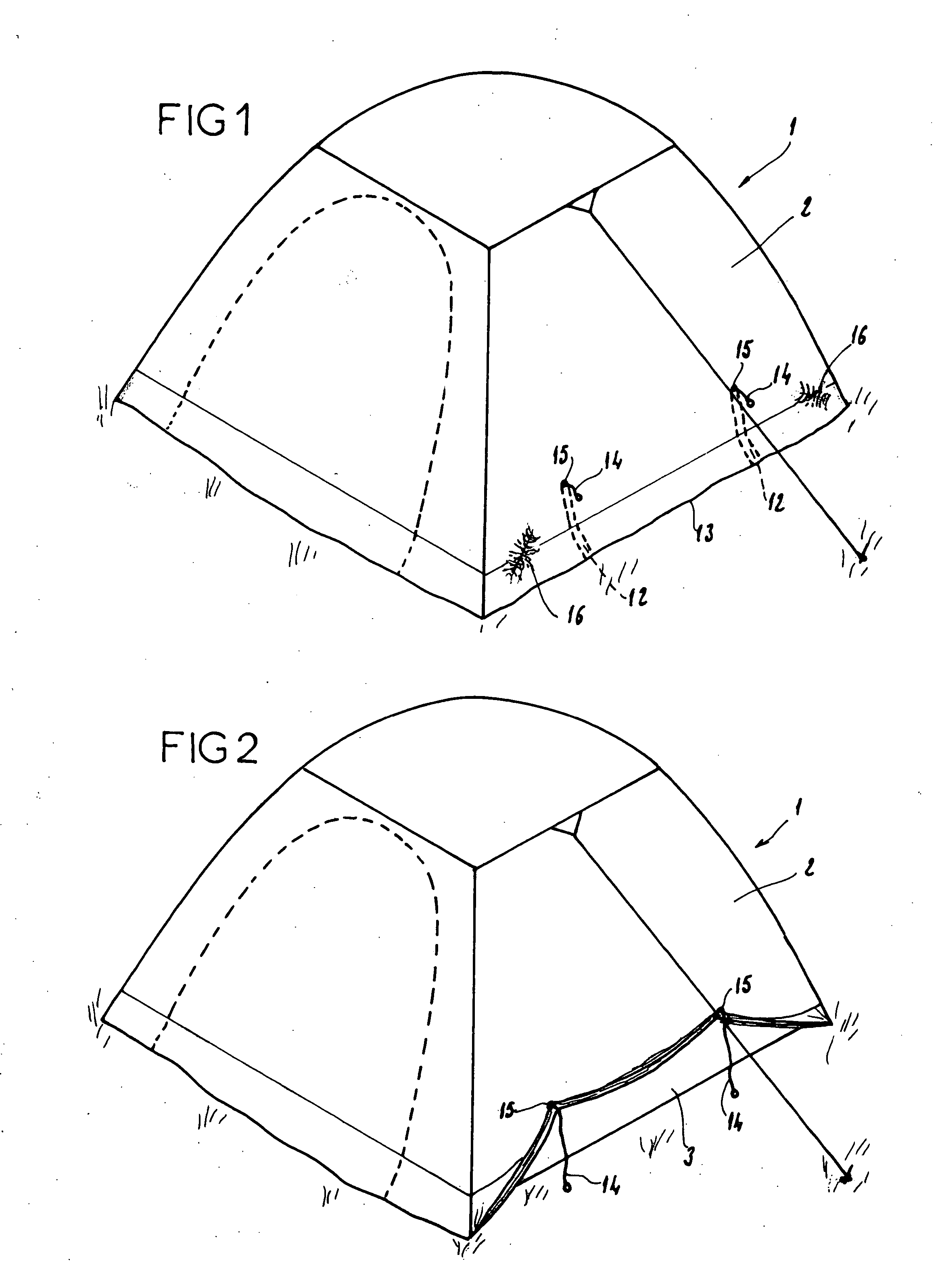
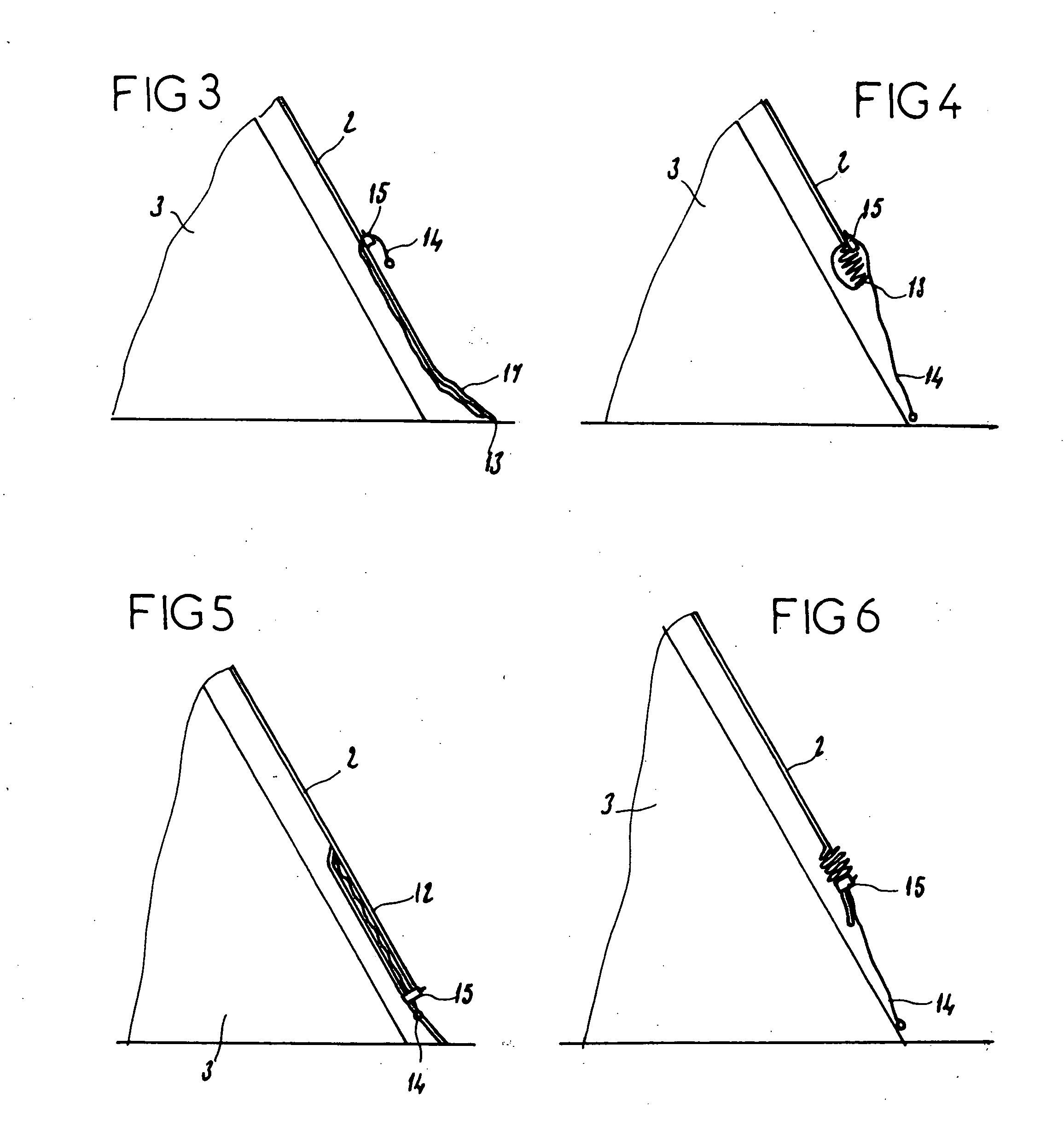
Referring first of all to FIGS. 1 and 2, it can be seen that the tent comprises a frame that supports an outer wall 2 and an inner wall 3, these two walls being superposed and defining a layer of air between themselves.

The frame of the tent is not the subject of the invention and will not be described in further detail. Usually, the tent is also provided with a door shown in dashes in FIGS. 1 and 2.

Note also that the tent is equipped with a groundsheet 5, which, with the inner wall 3, defines a room in the tent.

Referring to FIG. 7, it can be seen that a large part of the inner wall 3 is an air-permeable zone 7.

It will also be observed that the outer wall 2 has two openings 9, these openings 9 also being formed in the upper part of the outer wall 2 so that the openings 9 face the air-permeable zone of the inner wall 3.

These openings 9 which are shown schematically can be opened or closed at will.

Notice too that the outer wall 2 is provided with two sleeves 12; these two ...


PUM


Abstract

The tent (1) according to the invention comprises a frame supporting:
    • an inner wall (3) defining with a groundsheet (5) a room, the inner wall having in its upper part an air-permeable zone (7), and an outer wall (2) superposed on the inner wall (3) and defining with the latter a layer of air, the outer wall having at least one opening (9) facing the air-permeable zone (7) of the inner wall (3), characterized in that the lower border (13) of the outer wall (2) is provided with raising means for moving the lower border from a position in which the border is in contact with the surface to a position in which the lower border (13) is raised to a distance from this surface.

Description

TECHNICAL FIELD OF THE INVENTION This application claims the benefit of French Application number 03.07980, filed Jul. 1, 2003, incorporated herein by reference. TECHNICAL FIELD OF THE INVENTION The present invention relates to a camping tent and more particularly to an arrangement for controlling the circulation of air inside the tent. BACKGROUND OF THE INVENTION Conventionally, a camping tent is composed of at least one wall of textile material supported by a frame. The frame generally consists of hoops over which the wall is stretched. In the usual way, the tent may also include a part in which two walls, namely an inner wall and an outer wall are superposed. In such a case, the inner wall together with a groundsheet defines a closed space which forms a room. The inner wall consists at least in part of an air-permeable textile material. This air-permeable part is generally situated in the upper part of the tent. The outer wall is made of a completely impermeable material, a...

Claims


Application Information

Patent Timeline
IPC IPC(8): E04H15/14E04H15/32
CPCE04H15/32E04H15/14
Inventor BESSE, STEPHANE
Owner APPL DES GAZ AG
Why Eureka
Try Eureka