Sun tracking device for photovoltaic power generation

A technology of solar tracking and photovoltaic power generation, applied in photovoltaic power generation, solar thermal devices, heating devices, etc., can solve the problems of large-scale application of tracking brackets, poor adaptability to the environment, and large foundation volume, etc., to achieve large-scale Design, construction and maintenance are convenient, and the effect of improving power generation

Active Publication Date: 2017-01-04
丁慈鑫 +3
View PDF5 Cites 9 Cited by
  • Summary
  • Abstract
  • Description
  • Claims
  • Application Information

AI Technical Summary

Problems solved by technology

[0002] Since 2009, my country has launched large-scale photovoltaic power generation market applications. It is expected that through years of continuous national policy support and promotion, photovoltaic power generation applications will be promoted through two paths of technological progress and large-scale development, and finally achieve grid parity, thereby replacing fossil energy. Purpose, among them, the solar tracking bracket is one of the fast-growing branch technical solutions, which has playe

Method used


Image

  • Sun tracking device for photovoltaic power generation
  • Sun tracking device for photovoltaic power generation
  • Sun tracking device for photovoltaic power generation

Examples


Embodiment 1

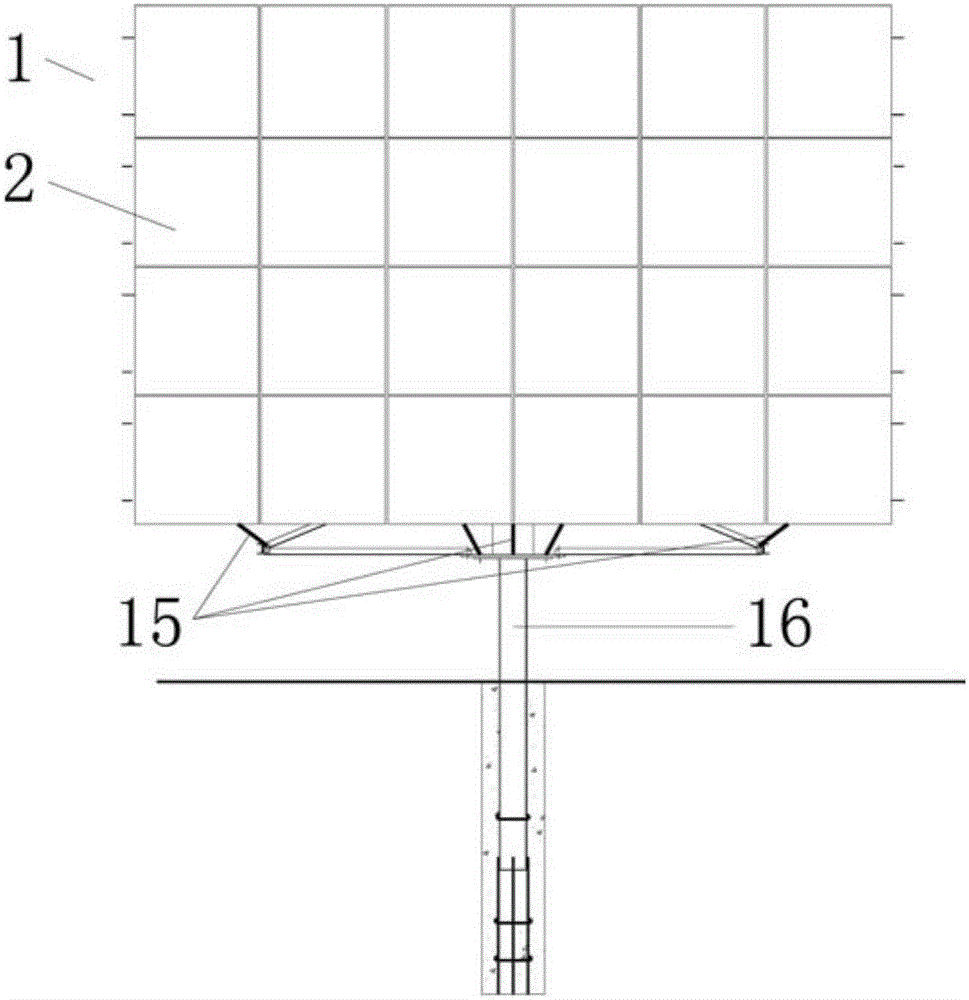
[0057] Such as figure 1 , 2 , 3, and 5, the tracking bracket 1 includes: a pile 16, a casing 8, a steel wheel 12, and a photovoltaic module plate fixing plate;

[0058] The pile 16 is a steel pipe or reinforced concrete material with a circular cross-section, which can be solid or hollow. The part embedded in the ground is called a pile, and the protruding part is called a column. And in order to enhance the anchoring effect on the ground, the bottom of the pile 16 is welded with an anchor bar 161, and the periphery of the buried part is poured and compacted with concrete 162. The axis line of the pile column 16 is perpendicular to the ground. When the pile 16 is made of steel pipe material, concrete is poured into the steel pipe to greatly improve the bending, shearing and torsional performance of the pile 16;

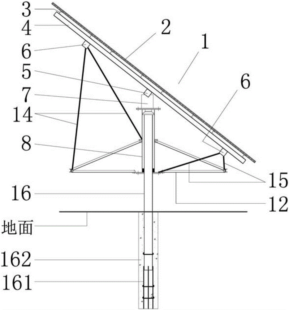
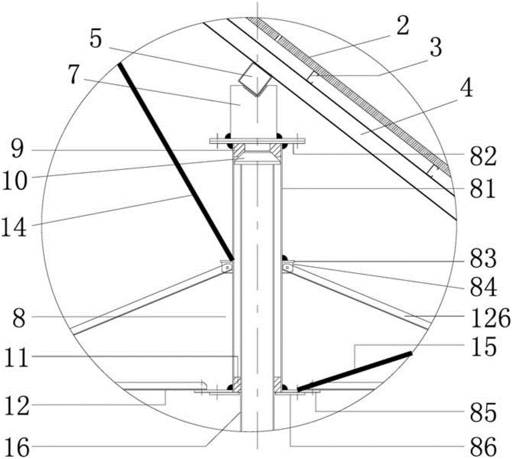
[0059] The photovoltaic module board 2 is installed on the horizontal purlin 3, and the horizontal purlin 3 is installed on the inclined beam 4, and the inclined b...

Embodiment 2

[0076] Such as Figure 4As shown, the only difference from the first implementation is that the combined structure of the pile 16 and the casing 8 has another form. The vertical support force of the pile 16 to the casing 8 is not at the top of the pile 16, but at the top of the casing 8. bottom of. A support flange 163 is welded at the waist of the pile 16. When the sleeve is inserted into the pile, the bottom surface of the sleeve 8 just sits on the surface of the support flange 163, forming the vertical support of the pile 16 to the sleeve 8. The upper surface of the large flange 163 and the bottom surface of the sleeve pipe 8 and the flange 85 at the bottom of the pipe are the sliding friction surfaces. In the inner cavity of the casing 8, two radial positioning bearings are set to realize the radial positioning support. The lower radial positioning support is a split bearing bush 11, and the upper radial positioning support is a circular sleeve 111. There is a supporting...

Embodiment 3

[0079] Such as Figure 17 As shown, on the basis of the tracking bracket in Embodiment 1, firstly, the connection mode between the inclined beam 4 and the horizontal beam 5 is changed to the connection mode of the hinge 24, and the inclined beam 4 can rotate around the axis of the hinge 24, and the high position The horizontal subbeam 6 and the high subbeam support rod 14 or the low subbeam support rod 15 under the horizontal subbeam 6 of the low position are changed to the high position adjustable support rod 141 and the low position adjustable support rod 151 of the telescopic adjustment length, and the high position The upper and lower ends of the adjustable support rod 141 and the low-position adjustable support rod 151 are connected by hinges, and a triangular support bracket 25 and a push rod support 29 are added to the casing 8, and finally a simple manual push rod 26 is set, and the Use the manual push rod 2 to adjust the inclination angle of the photovoltaic module bo...


PUM


Abstract

The invention relates to the technical field of photovoltaic power generation, in particular to a sun tracking device for photovoltaic power generation. The sun tracking device is characterized in that a pile and a sleeve type structure combination is adopted, a winch drives a steel wire rope to pull a plurality of unpowered passive tracking supports to rotate to track change of solar azimuth; an dip angle adjusting mechanism can be arranged to enable a photovoltaic module board to rotate around a horizontal axis to track changes of solar elevation angle; a mirror reflecting board is arranged on the lower border of the photovoltaic module board to enhance light harvesting energy of the photovoltaic module board. The turn-off feature of the steel wire rope is utilized, and plane arrangement and elevation arrangement of the tracking supports are high in flexibility and quite adaptable to block foundations with irregular planes and land conditions with uneven sites; various deformation of the steel wire rope is consumed and compensated by the aid of a gravity tensioning balancer, and stable operation of a transmission system is sustained; the sun tracking device is high in cost performance, suitable for largescalization design of the supports and high in capability of fitting for complicated project conditions.

Description

technical field [0001] The invention relates to the field of photovoltaic power generation equipment, in particular to a solar tracking device for photovoltaic power generation. Background technique [0002] Since 2009, my country has launched large-scale photovoltaic power generation market applications. It is expected that through years of continuous national policy support and promotion, photovoltaic power generation applications will be promoted through two paths of technological progress and large-scale development, and finally achieve grid parity, thereby replacing fossil energy. Purpose, among them, the solar tracking bracket is one of the fast-growing branch technical solutions, which has played a role in promoting the increase of power generation, but the existing tracking bracket has the following disadvantages: complex structure, high cost, high failure rate, difficult maintenance, Poor adaptability to the environment, difficult construction, larger foundation volum...

Claims


Application Information

Patent Timeline
IPC IPC(8): H02S20/32F24J2/38F24J2/54F24S50/20
CPCF24S30/40F24S50/20F24S2030/11H02S20/32Y02E10/47Y02E10/50
Inventor 丁慈鑫丁树东丁宁丁垟
Owner 丁慈鑫
Why Eureka
Try Eureka