Electronically expiring device

a technology of electronic expiration and device, applied in the field of time measurement methods and devices, can solve problems such as the self-destruct of devices or components of devices

Inactive Publication Date: 2005-01-06
IBM CORP
View PDF6 Cites 19 Cited by
  • Summary
  • Abstract
  • Description
  • Claims
  • Application Information

AI Technical Summary

Problems solved by technology

After the predetermined time period has elapsed, the device or a com

Method used


Image

  • Electronically expiring device
  • Electronically expiring device

Examples


Embodiment Construction

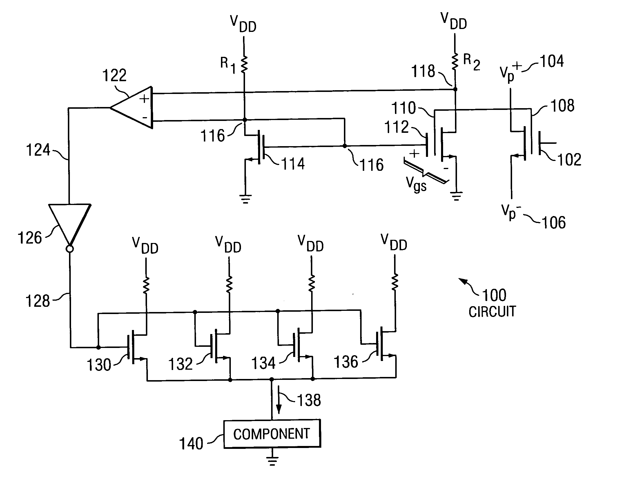
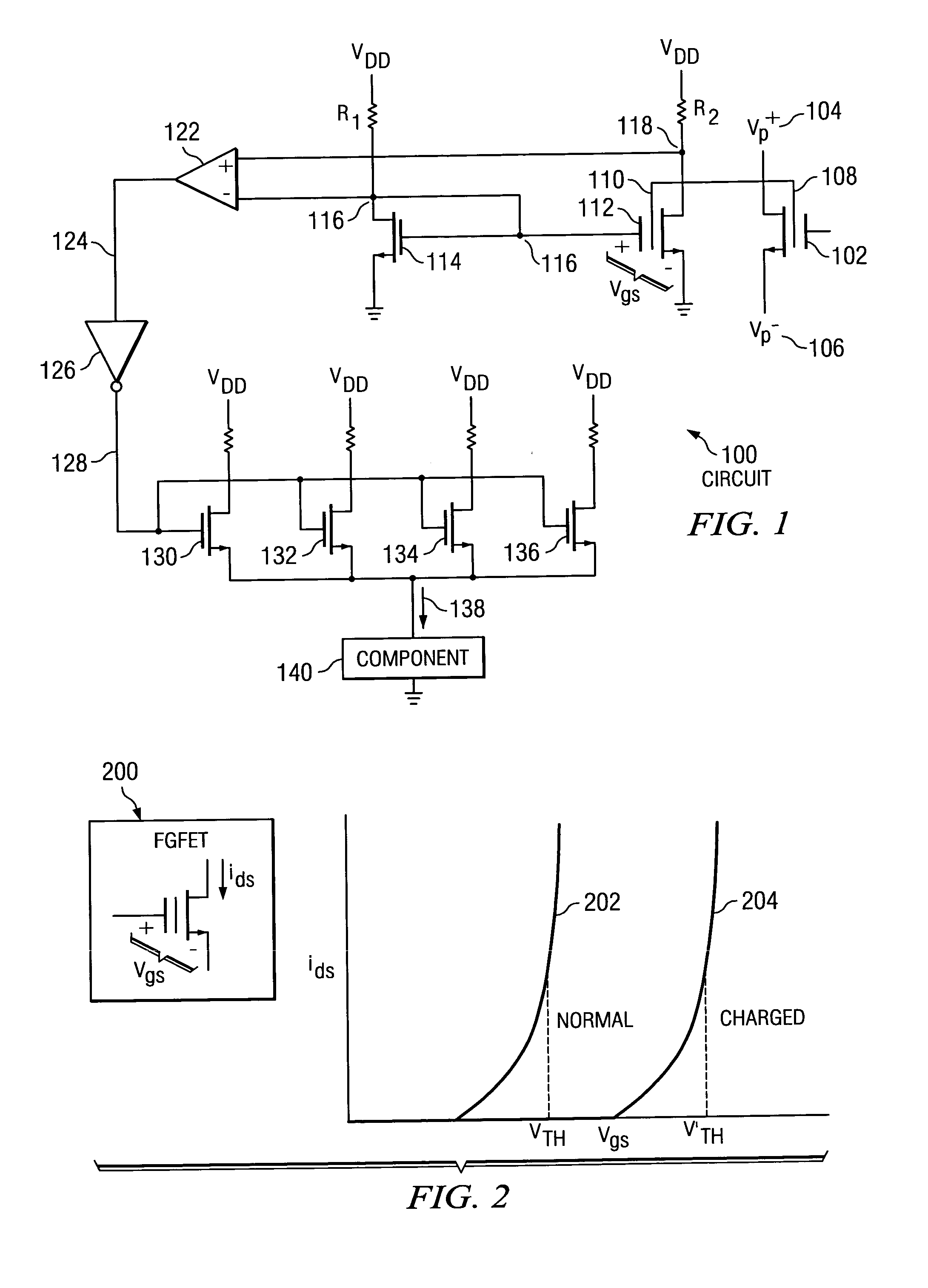
[0013] In the preferred embodiment of the present invention, a device self-destructs when connected to a power source after a predetermined time period has elapsed. The device contains its own internal time cell. The state of the time cell is read and a determination is made as to whether or not the predetermined time period has elapsed since the time cell was programmed. If the predetermined time period has elapsed, the device or a component of the device self-destructs when connected to a power source.

[0014] There are many possible applications for a preferred embodiment of the present invention. For example, there are credit card-like and smart card-like “value cards” for telephone service, store discounts, frequent flyer miles, purchases, and hotel door access, which may have expiration dates or may have additional benefits if an expiration date is incorporated into the value card. Business models for many of these cards might be improved if the card expired on its own rather t...


PUM


Abstract

The present invention relates to a method and system for expiring a device after a predetermined time period has elapsed. A device, which contains its own internal time cell, is designed to stop working or self-destruct after a predetermined time period has expired. The device uses its own time cell so that the elapsed time period is not altered through an external time source. After the predetermined time period has elapsed, the device or a component of the device self-destructs when connected to a power source.

Description

CROSS REFERENCE TO RELATED APPLICATIONS [0001] The present invention is related to U.S. patent applications entitled “SENSING METHODS AND DEVICES FOR A BATTERYLESS, OSCILLATORLESS, BINARY TIME CELL USABLE AS AN HOROLOGICAL DEVICE”, Ser. No. 09 / 703,340 (attorney docket number AUS9-2000-0733-US1) filed on Oct. 31, 2000; and “SENSING METHODS AND DEVICES FOR A BATTERYLESS, OSCILLATORLESS, ANALOG TIME CELL USABLE AS AN HOROLOGICAL DEVICE”, Ser. No. 09 / 703,334 (attorney docket number AUS9-2000-0734-US1) filed on Oct. 31, 2000; both of which are assigned to the same assignee and incorporated herein by reference.BACKGROUND OF THE INVENTION [0002] 1. Technical Field [0003] The present invention relates to horology and, in particular, to methods and devices for time measurement using an electrical time base. Still more particularly, the present invention provides a method and system for expiring a device after a predetermined amount of time has elapsed. [0004] 2. Description of Related Art [0...

Claims


Application Information

Patent Timeline
IPC IPC(8): G04F1/00G06K19/073
CPCG06K19/073G04F1/005
Inventor BERSTIS, VIKTORS
Owner IBM CORP
Why Eureka
Try Eureka