Form support for supporting a disposable mold form

a mold form and support technology, applied in the direction of forms/shuttering/falseworks, shaping building parts, construction, etc., can solve the problems of corroding and expanding of the mold form, affecting the construction effect,

Inactive Publication Date: 2005-01-06
STEGMEIER
View PDF18 Cites 9 Cited by
  • Summary
  • Abstract
  • Description
  • Claims
  • Application Information

AI Technical Summary

Benefits of technology

[0014] Another objective is to provide a form support that includes a tie wire that is adapted to support the disposable mold form so that the weight o

Problems solved by technology

The problem with this approach is that the tie wire is sometimes not removed until the coping has entirely cured, at which point the coping often tends to bind to the tie wire and thereby prevent it from being removed from the coping.
If a portion of the tie wire remains near the surface of the coping, the remnant will corrode and expand, which in

Method used


Image

  • Form support for supporting a disposable mold form
  • Form support for supporting a disposable mold form
  • Form support for supporting a disposable mold form

Examples


Embodiment Construction

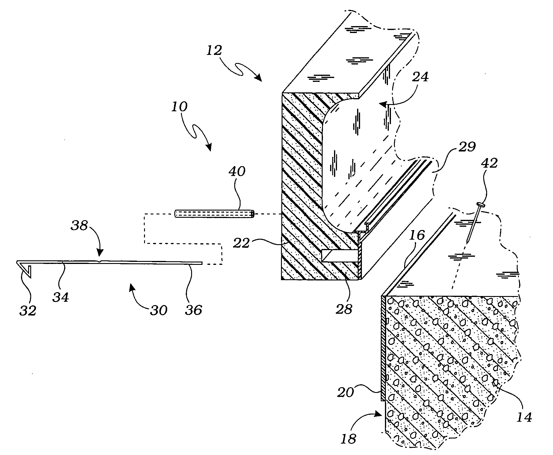
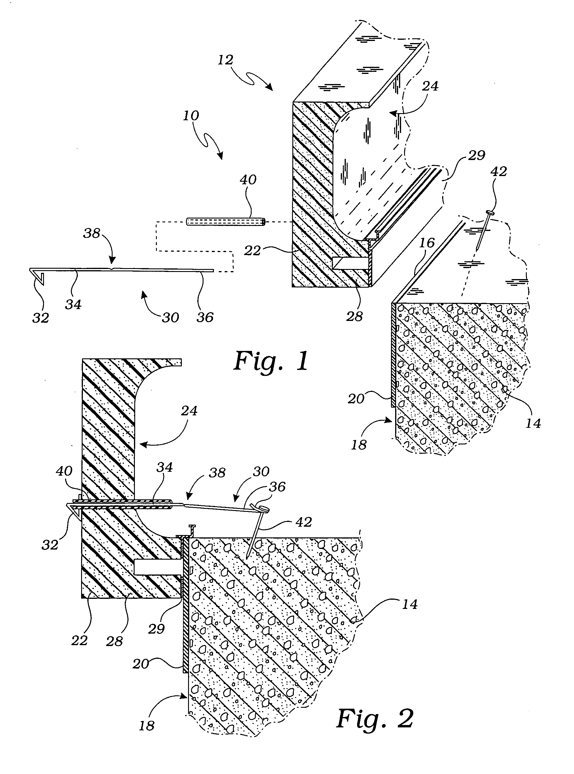
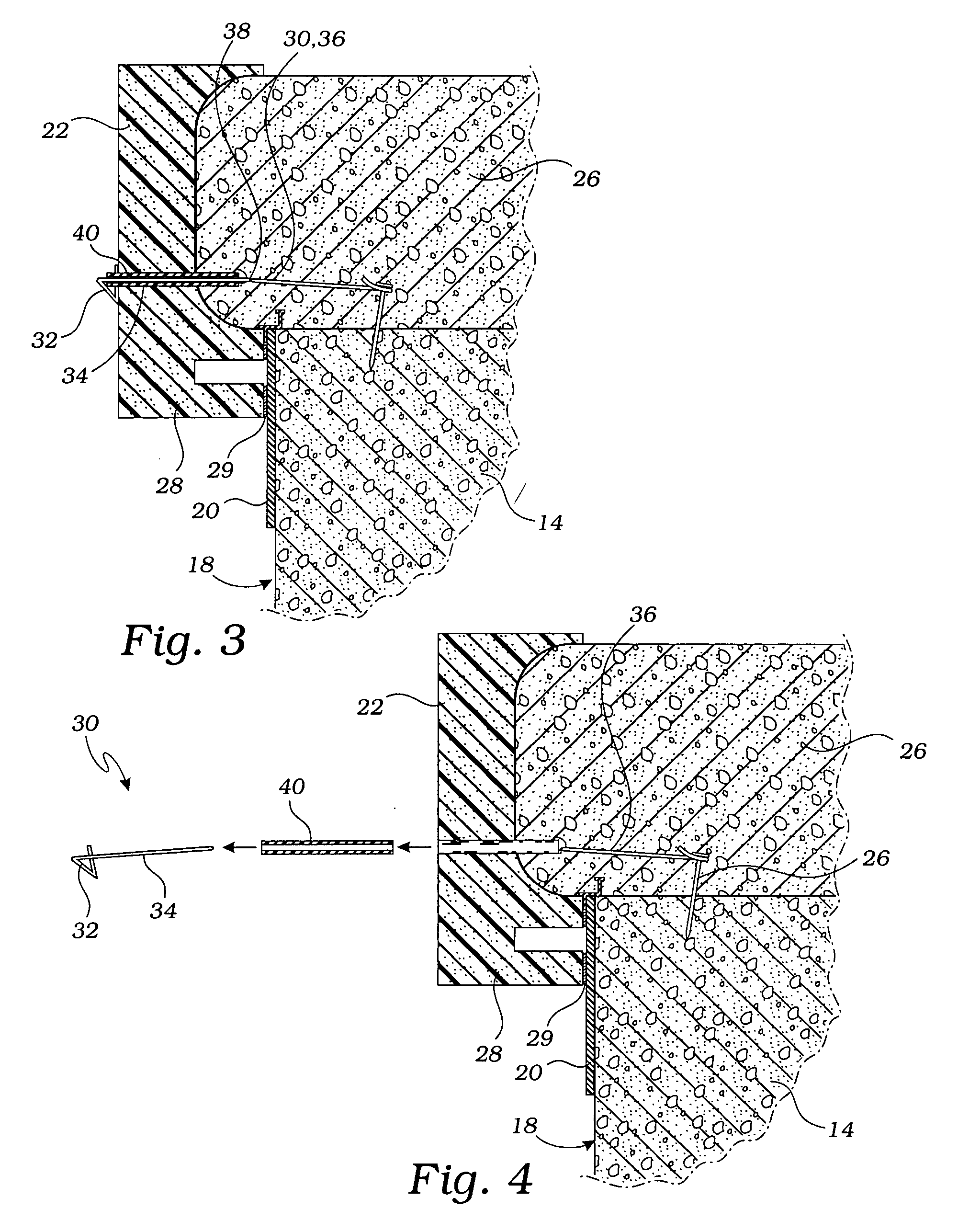
[0022] The above-described drawing figures illustrate the invention, a form support 10 for supporting a disposable mold form 22 mounted on a bond beam 14 for forming a cement coping 26 during the construction of a swimming pool. The form support 10 includes a tie wire 30 and an elongate tube 40, which are described in greater detail below

[0023]FIG. 1 illustrates how the disposable mold form 22 is mounted on the bond beam 14, which is formed by the upwardly extending side walls of the swimming pool. The bond beam 14, and the entirety of the upwardly extending side walls, may be formed in any conventional manner, and ordinarily are fabricated of concrete and integral with a bottom wall (not shown). The generally vertical or upwardly extending walls are enlarged somewhat at their upper ends to form the bond beam 14 which is rather standard practice. The bond beam 14 has an upper edge 16 and an inner face 18 or surface. The inner face 18 has a water-impervious finish 20 secured thereto...


PUM


Abstract

A form support for supporting a disposable mold form. The disposable mold form is adapted to be mounted on a bond beam for forming a cement coping. The form support includes a tie wire and an elongate tube. The tie wire has a head, an elongate midsection, and an end portion. The elongate midsection and the end portion are separated by a weakened portion. The tie wire is adapted to be positioned through the disposable form mold such that the head abuts the disposable mold form, the elongate midsection extends through the disposable mold form, and the end portion extends over the bond beam. The elongate tube is shaped to fit around the tie wire such that the elongate tube extends from the head to the vicinity of the weakened portion.

Description

BACKGROUND OF THE INVENTION [0001] 1. Field of the Invention [0002] This invention relates generally to the construction of swimming pools and the like and, more particularly, to a form support for supporting a disposable mold form for molding a concrete coping along the upper edge of a swimming pool. [0003] 2. Description of Related Art [0004] In constructing a concrete swimming pool, the commonly followed practice is to first build the upwardly extending concrete side walls and bottom wall therefor usually as an integer and by a technique known as the gunite process. After the concrete side walls have at least partially cured, a water impervious layer, such as tile 20, is installed over the concrete. [0005] Once the tile 20 has been installed, concrete coping is formed on the upper portion of the concrete sidewall, known as the bond beam. The currently preferred method of forming the concrete coping involves the use of a disposable mold form is bonded to the tile 20 for forming th...

Claims


Application Information

Patent Timeline
IPC IPC(8): E04G11/36
CPCE04G11/365
Inventor MUSSER, DARELL WAYNE
Owner STEGMEIER
Why Eureka
Try Eureka