Compact radial gap machine and method for high strength undiffused brushless operation

a compact, undiffused technology, applied in the direction of windings, synchronous machines with stationary armatures and rotating magnets, dynamo-electric components, etc., can solve the problems of low inductance, current ripple must be controlled, and the need for sophisticated approach, so as to increase the resultant flux

Inactive Publication Date: 2005-01-06
UT BATTELLE LLC
View PDF12 Cites 21 Cited by
  • Summary
  • Abstract
  • Description
  • Claims
  • Application Information

AI Technical Summary

Benefits of technology

The invention is also practiced in a method of controlling flux in a brushless electrical machine, the method comprising: inducing a first flux in a rotor from a stator across a radial air gap by conducting a current in a primary excitation winding on the stator; positioning a first excitation coil at one end of the rotor; conducting a direct current through the first excitation coil so as to produce a second flux in the rotor across at least one axial air gap and to produce a resultant flux in radial air gap resulting from the first flux and the second flux; providing portions of PM material between poles in the rotor, which is of generally cylindrical shape, so as to convey the second flux to or from the radial air gap and to prevent leakage of the second flux in the rotor before reaching the radial air gap; conducting a direct current of a first polarity through the first excitation coil, so as to increase resultant flux in the radial air gap; and conducting a direct current of a second polarity through the first excitation coil so as to weaken resultant flux in the radial air gap.

Problems solved by technology

One drawback of the PM motor for the above-mentioned application is that the variation of the air gap flux produced by the PM rotor is limited, and therefore, a sophisticated approach is required for high speed, field weakening operation.
Another constraint is that inductance is low, which means that current ripple must be controlled.
It is understood by those skilled in the art that a PM electric machine has the property of high efficiency and high power density, however, the air gap flux density of a PM machine is limited by the PM material, which is normally about 0.8 Teslas and below.
A PM machine cannot operate at an air gap flux density as high as desired.
When considering a radial gap configuration for undiffused, high strength operation, several problems have to be overcome.

Method used


Image

  • Compact radial gap machine and method for high strength undiffused brushless operation
  • Compact radial gap machine and method for high strength undiffused brushless operation
  • Compact radial gap machine and method for high strength undiffused brushless operation

Examples


Embodiment Construction

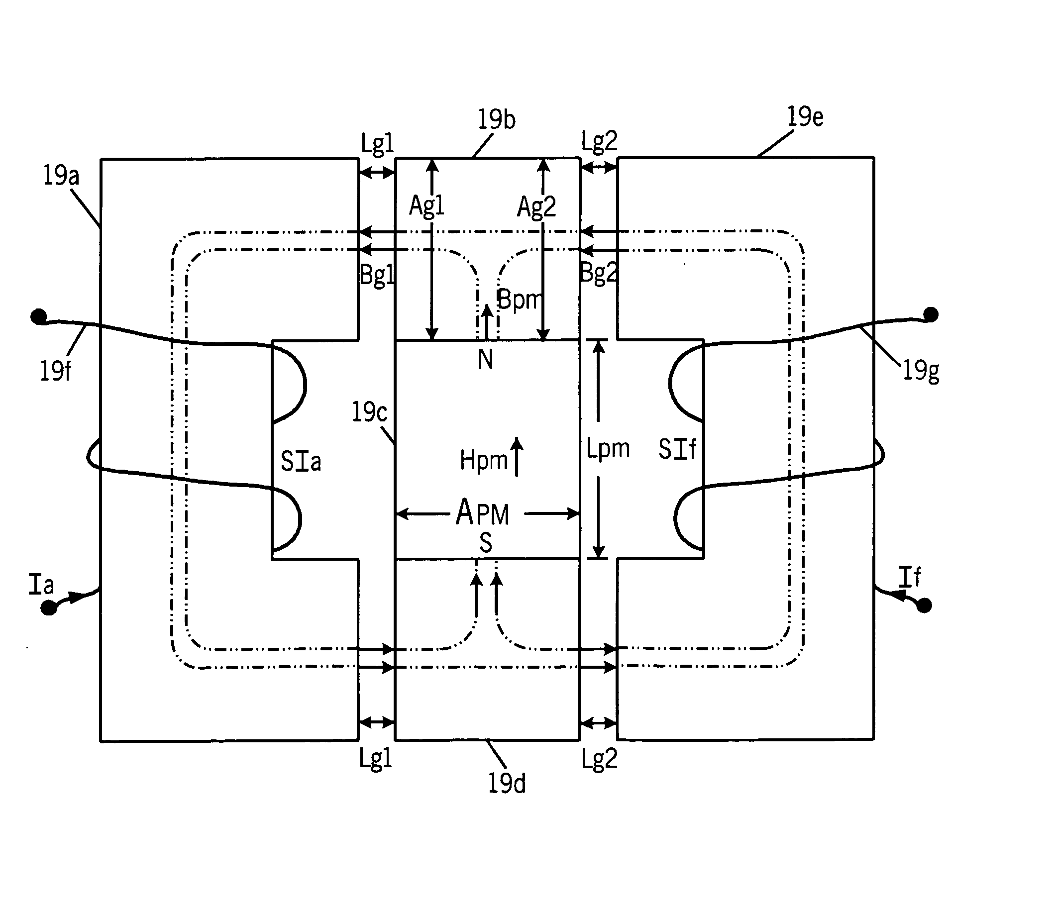
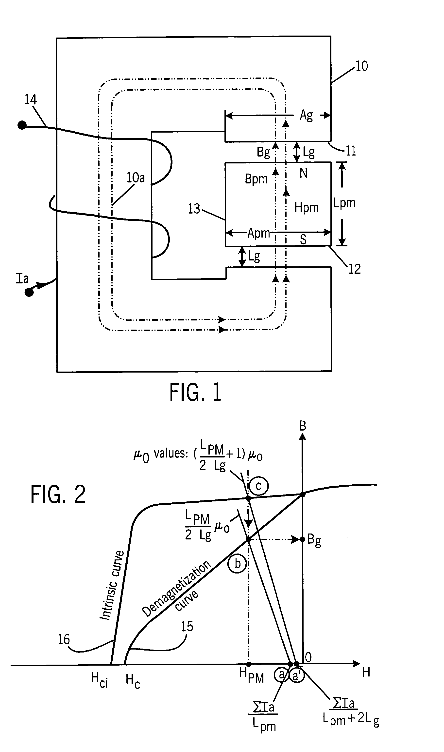
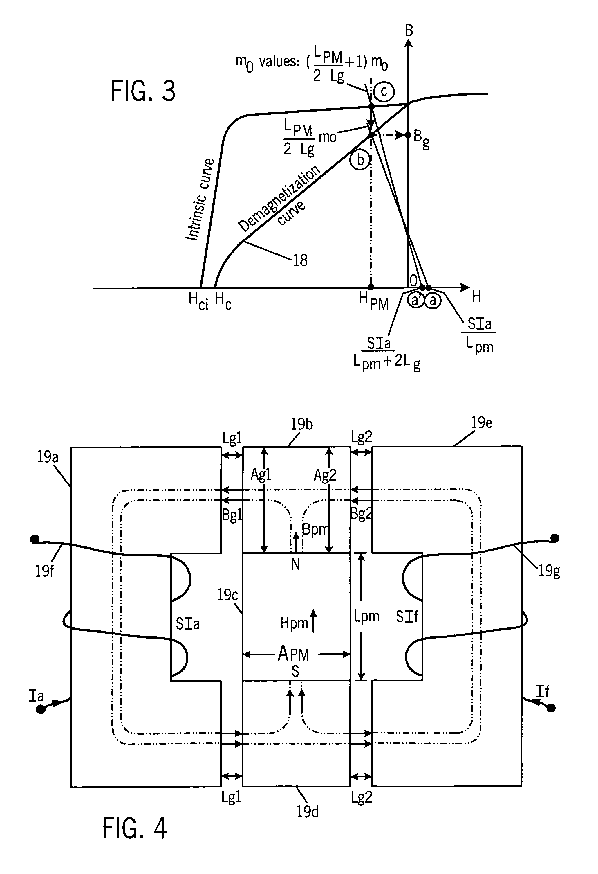
The principle of a high strength, undiffused brushless machine has been previously disclosed in the Hsu, U.S. Pat. No. 6,573,634, issued Jun. 3, 2003, and Hsu, U.S. patent application Ser. No. 10 / 668,586 filed Sep. 23, 2003, the disclosures of which are hereby incorporated by reference. The following theoretical description may be of benefit to an understanding of the advantages provided by the present invention. The conclusions of the following derivations show that significant field enhancement can only be achieved through an additional flux path excited through an excitation winding. A significant field enhancement is achieved through the additional d-axis current in a conventional PM (permanent magnet) machine. The derivations also show that the field weakening can be achieved without demagnetizing the PM elements. A simple PM magnetic circuit that has the PM elements connected in series with the air gaps and the return magnetic core is shown in FIG. 1. This circuit represents ...


PUM


Abstract

A radial gap brushless electric machine (30) having a stator (31) and a rotor (32) and a primary air gap (34) also has at least one stationary excitation coil (35a, 36a) separated from the rotor (32) by a secondary air gap (37a, 37b) so as to induce a secondary flux in the rotor (32) which controls a resultant flux in the main air gap (34). Permanent magnetic (PM) material (38) is disposed in spaces between the rotor poles (A-H) to inhibit the secondary flux from leaking from said pole portions (A-H) prior to reaching the main air gap (34). By selecting the direction of current in the stationary excitation coil (35a, 36a) both flux enhancement and flux weakening are provided for the main air gap (34). A method of non-diffused flux enhancement and flux weakening for the machine is also disclosed.

Description

TECHNICAL FIELD The field of the invention is brushless machines, including both AC and DC machines, including both motors and generators, and including induction machines, permanent magnet (PM) machines and switched reluctance machines. DESCRIPTION OF THE BACKGROUND ART There are three major types of brushless electric machines available for the electric vehicle (HV) and hybrid electric vehicle (HEV) drive systems. These are the induction machine, the PM machine, and the switched-reluctance machine. Permanent magnet (PM) machines have been recognized for having a high power density characteristic. A PM rotor does not generate copper losses. One drawback of the PM motor for the above-mentioned application is that the variation of the air gap flux produced by the PM rotor is limited, and therefore, a sophisticated approach is required for high speed, field weakening operation. Another constraint is that inductance is low, which means that current ripple must be controlled. It is ...

Claims


Application Information

Patent Timeline
Patent Type & Authority Applications(United States)
IPC IPC(8): H02K21/04
CPCH02K21/046
Inventor HSU, JOHN S.
Owner UT BATTELLE LLC
Why Eureka
Try Eureka