Arrangement of a running roller on a coupling journal of a moveable shaft coupling

Inactive Publication Date: 2005-01-06
HENKEL JURGEN +7
View PDF40 Cites 0 Cited by
  • Summary
  • Abstract
  • Description
  • Claims
  • Application Information

AI Technical Summary

Benefits of technology

[0018] In another example embodiment of the arrangement of a running roller on a coupling journal according to the present invention, the formation of a special middle joint portion on a fixing insert is eliminated, and, instead, in each case a simple fixi

Problems solved by technology

The sliding movements of the coupling journal in relation to the associated ball head, require a costly grinding or honing process in order to produce the

Method used


Image

  • Arrangement of a running roller on a coupling journal of a moveable shaft coupling
  • Arrangement of a running roller on a coupling journal of a moveable shaft coupling
  • Arrangement of a running roller on a coupling journal of a moveable shaft coupling

Examples


Embodiment Construction

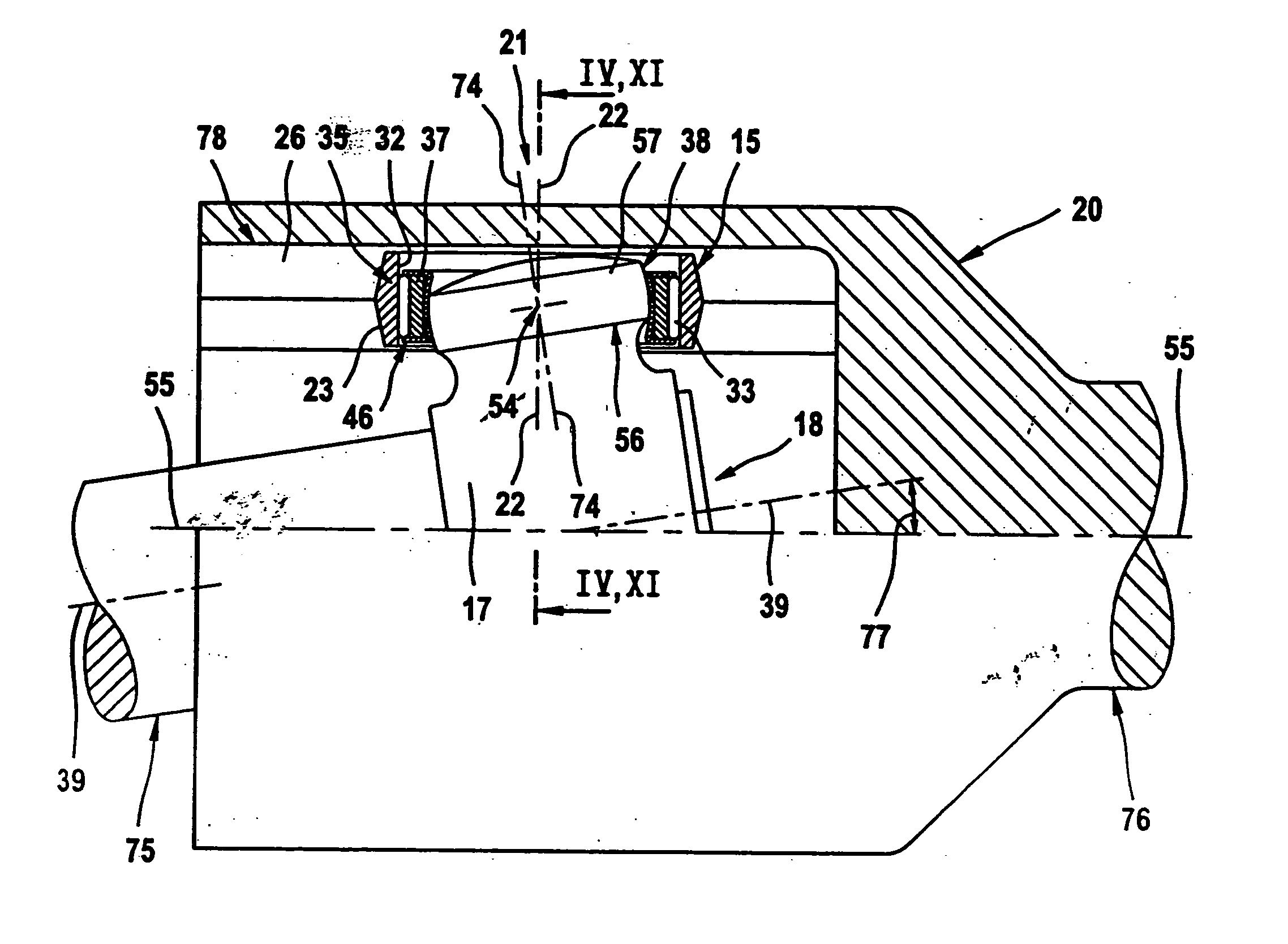
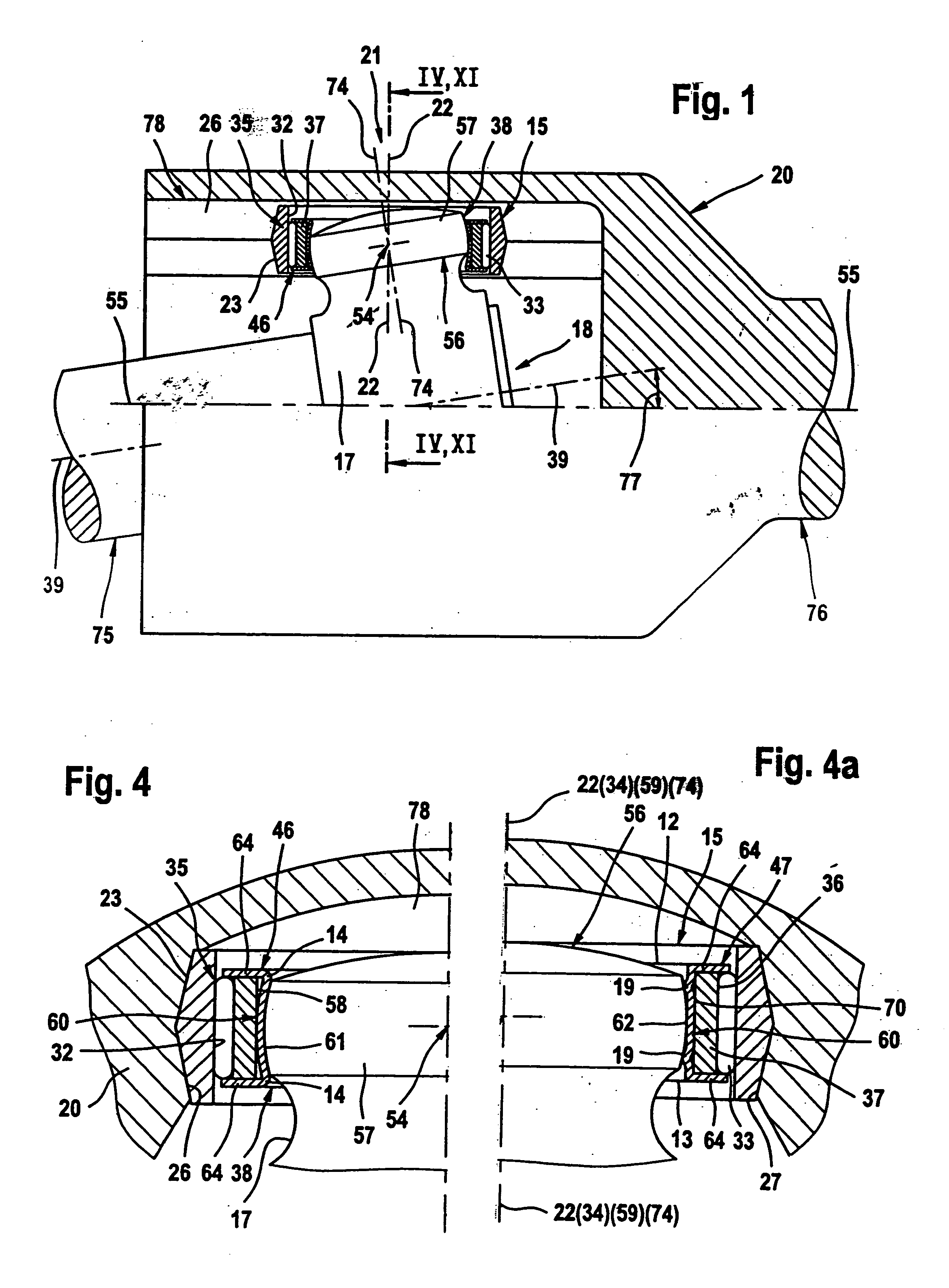
[0030] Referring first to FIGS. 1, 2 and 4, a moveable shaft coupling 21 is used for the rotationally fixed connection of two drive shafts 75 and 76 which with respect to their central axes 39-39 and 55-55 may assume a bending position forming a bending angle 77 or a straight position with their central axes being aligned coaxially.

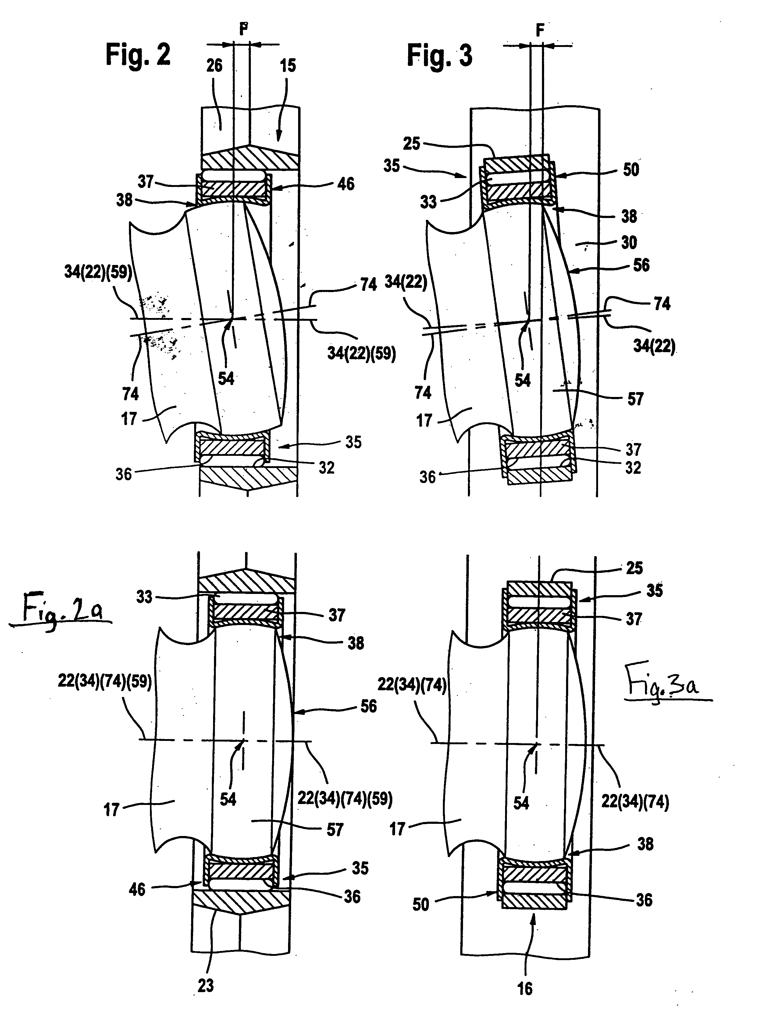
[0031] That coupling half 18 of the shaft coupling 21 which is assigned fixedly in terms of movement to the drive shaft 75 includes at least one coupling journal 17 which is oriented with its central axis 74-74 perpendicular to the central axis 39-39 of the drive shaft 75 and which is connected rotationally and pivotably movably to a running roller 15 by a series arrangement that includes a ball joint 38 and a radial rolling bearing 35.

[0032] The complementary coupling half assigned fixedly in terms of movement to the drive shaft 76 is configured as a coupling drum 20 which has on its inner circumference, for each running roller 15, an axial groove 78 w...


PUM


Abstract

In an arrangement of a running roller on a coupling journal of a coupling half of a moveable shaft coupling, a radial rolling bearing, the inner ring of which is connected to the coupling journal by a ball joint, is inserted into the running roller. In order to maintain an additional degree of freedom for the relative movements of the coupling journal in relation to the complementary coupling half in the directions perpendicular to the central axis of the latter, either the running face of the running roller is configured cylindrically or the rolling bearing is configured as a loose bearing.

Description

FIELD OF THE INVENTION [0001] The invention relates to an arrangement of a running roller on a coupling journal of a moveable shaft coupling. BACKGROUND INFORMATION [0002] In shaft couplings with a conventional arrangement of a running roller, it is essential that the two shafts to be coupled are capable, in relation to one another, of assuming “bending positions” of a static or dynamic type with respect to their axes of rotation and of executing axial movements, without non-uniformities in the rotational speed behaviour occurring on the shafts. [0003] In another arrangement of the running roller as described, for example, in German Published Patent Application No. 28 31 044, the connection of the inner ring of the rolling bearing to the associated ball socket of the ball joint is configured so that the inner ring and ball joint are produced in one piece, while, in order to maintain the additional degree of freedom of the cylindrical coupling journal in relation to the complementary...

Claims


Application Information

Patent Timeline
IPC IPC(8): F16D3/205
CPCF16D2003/2023F16D3/205F16D2003/2026
Inventor HENKEL, JURGENKOLLMANN, ANDREASMUNICH, PETERNIECHOJ, WOLFGANGRINDFLEISCH, OLAFSCHRODER, ROLFWENIGER, STEFANWORNER, GUNTER
Owner HENKEL JURGEN
Why Eureka
Try Eureka