
Eureka
For R&D, Eureka makes reading and utilizing patents & technical documents easy.
Eureka AIR
Designed for self-driven R&D workflows. Generate viable solutions, solve complex R&D challenges, empower your innovation with AI.

Eureka Materials
Designed for material experts only. Revolutionize your material R&D, from search, analyze, to developing new materials.

TechResearch
Generate reliable direction feasibility study reports for your R&D in just a few steps.

TechSeek
Discover and master advanced knowledge NOW. Basics, ideas, possibilities, all at once.

TechMind
As an expert in R&D Theories, TechMind can generates customized viable solutions instantly.

TechRisk
Analyze your overall solution with one click, know your potential R&D risks in advance.

TechMonitor
Get weekly tech updates, stay abreast of the latest tech innovations and key insights.
Device
- Summary
- Abstract
- Description
- Claims
- Application Information
AI Technical Summary
Benefits of technology
Problems solved by technology
Method used
Image

Examples
Example
DETAILED DESCRIPTION OF THE DRAWING
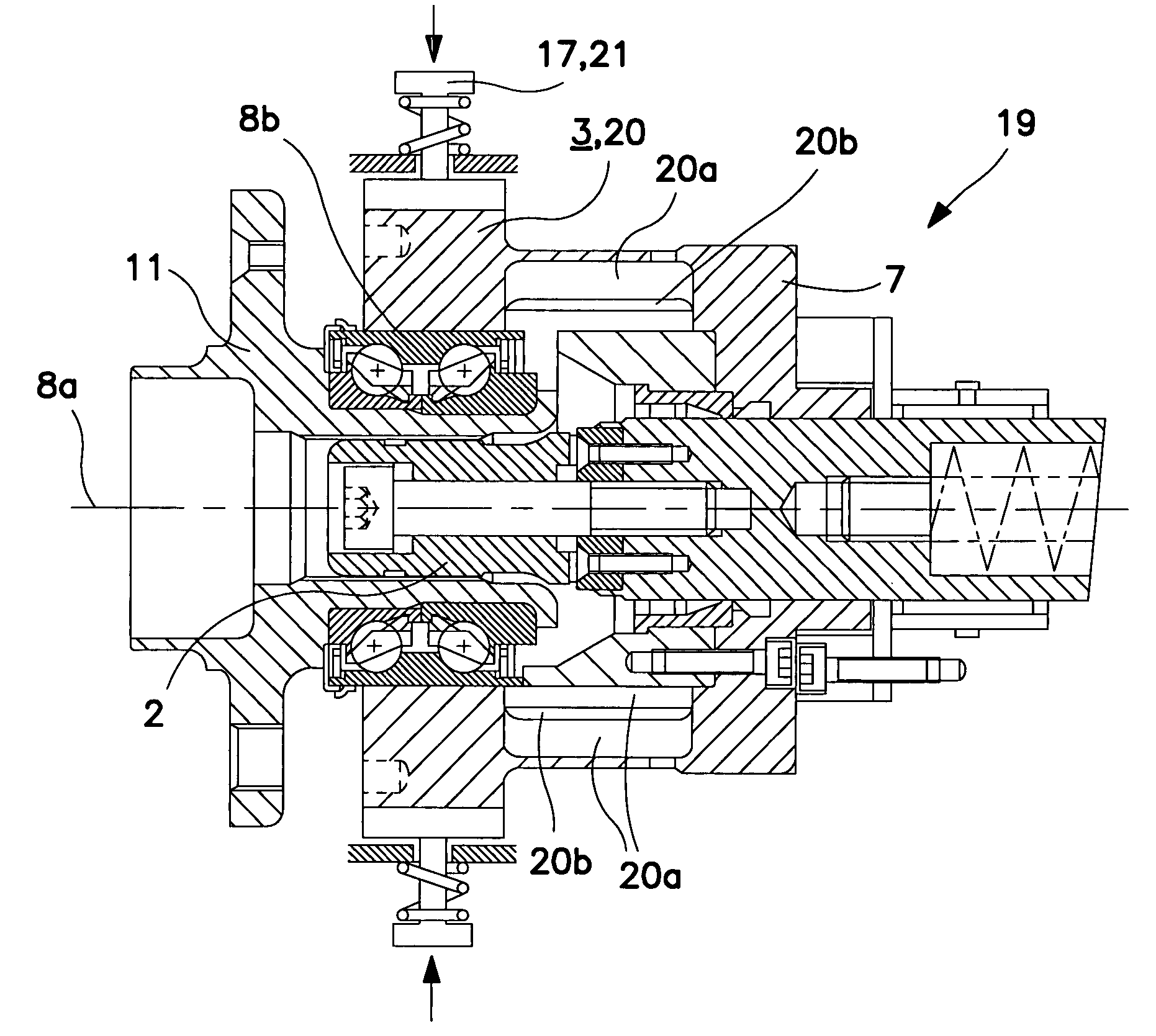
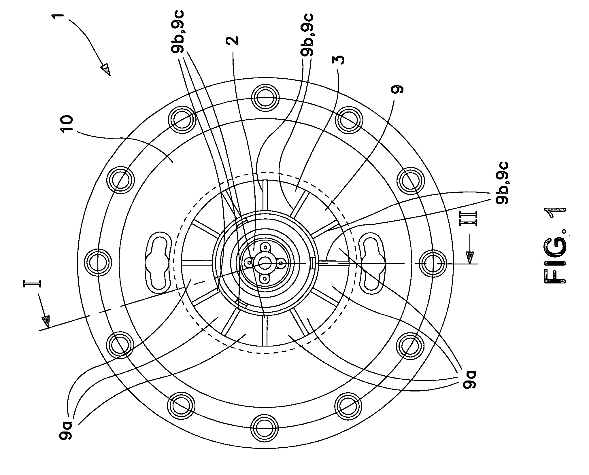
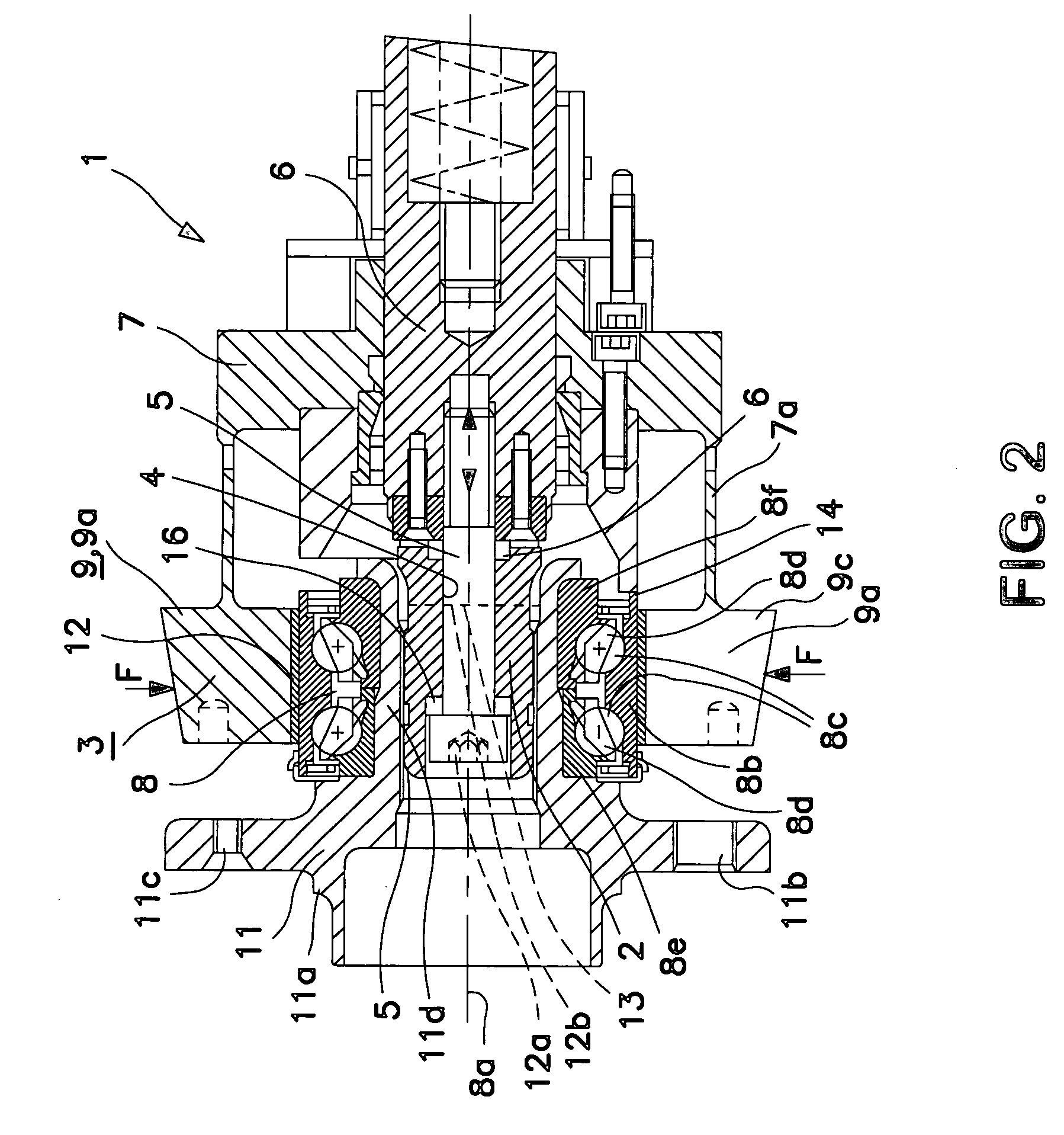
[0027]FIG. 1 shows a front view of a device 1 of the invention and in FIG. 2 is shown a longitudinal section through this device 1. The device 1 is substantially formed by an arbor 2 rotatable relative to the device and a clamping mechanism 3. The arbor 2 is rotationally symmetrical and provided with an axial through-bore 1. An axial bolt 5 extends through the through-bore 4 and the axial bolt 5 is axially screwed into a drive shaft 6. The drive shaft 6 is supported relative to the device, and therewith to a carrier 7, about the rotational axis 8a of a wheel bearing 8 in the carrier 7. With respect to carrier 7, the clamping mechanism 3, in the form of an elastic chuck 9, is fixed and the elastic chuck 9 comprises several clamping jaws 9a uniformly distributed at the circumferential side about the axis of rotation 8a.
[0028] In FIG. 1, the device 1 is depicted without the wheel bearing and with a front plate 10 which front plate 10 is omitted in t...
PUM
| Property | Measurement | Unit |
|---|---|---|
| Length | aaaaa | aaaaa |
| Force | aaaaa | aaaaa |
| Pressure | aaaaa | aaaaa |
Abstract
Description
Claims
Application Information
 - R&D Engineer
- R&D Manager
- IP Professional
- Industry Leading Data Capabilities
- Powerful AI technology
- Patent DNA Extraction
Browse by: Latest US Patents, China's latest patents, Technical Efficacy Thesaurus, Application Domain, Technology Topic, Popular Technical Reports.
© 2024 PatSnap. All rights reserved.Legal|Privacy policy|Modern Slavery Act Transparency Statement|Sitemap|About US| Contact US: help@patsnap.com