Pedal device for vehicle and automobile using the same
a technology for vehicles and brakes, applied in mechanical control devices, foot actuation initiations, instruments, etc., can solve the problems of inability to press the brake pedal with force, and the workload of drivers is larg
- Summary
- Abstract
- Description
- Claims
- Application Information
AI Technical Summary
Benefits of technology
Problems solved by technology
Method used
Image
Examples
first embodiment
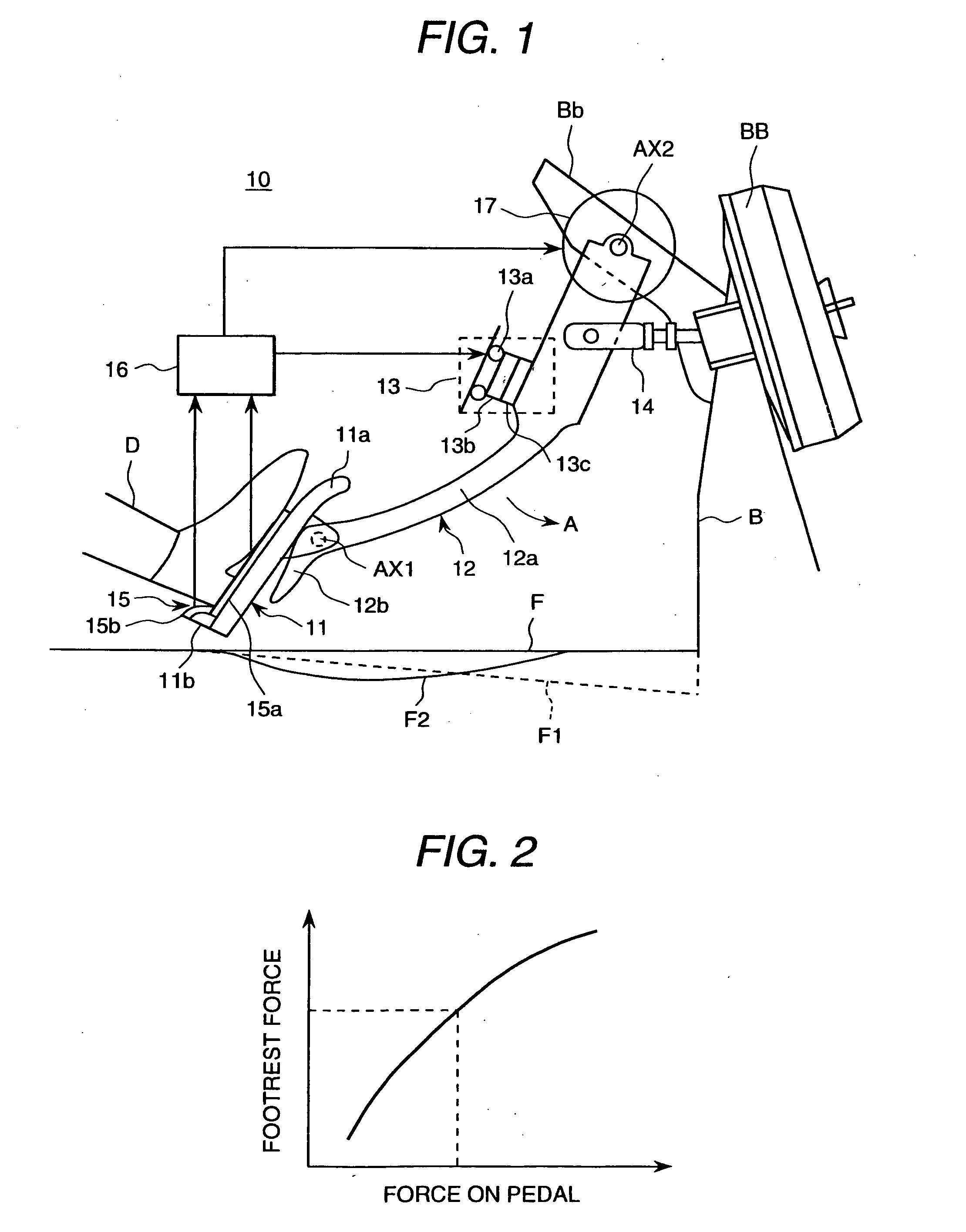
[0066] Here, the footrest function of the pedal device of the vehicle according to this embodiment is explained with reference to FIGS. 2 and 3. These figures are explanatory views of the footrest function of the pedal device of the vehicle according to the present invention.
[0067] Driver D's force-on-pedal and foot load are different in each driver. Then, footrest force calculation means 16 self-adjusts the footrest force by footrest means 13 according to the force-on-pedal and foot load of each driver.
[0068]FIG. 2 shows the relation between the force-on-pedal and the footrest force. As shown, footrest force calculation means 16 increases the amount of the energizing to coil 13a so that the footrest force may increase by increasing of the force-on-pedal.
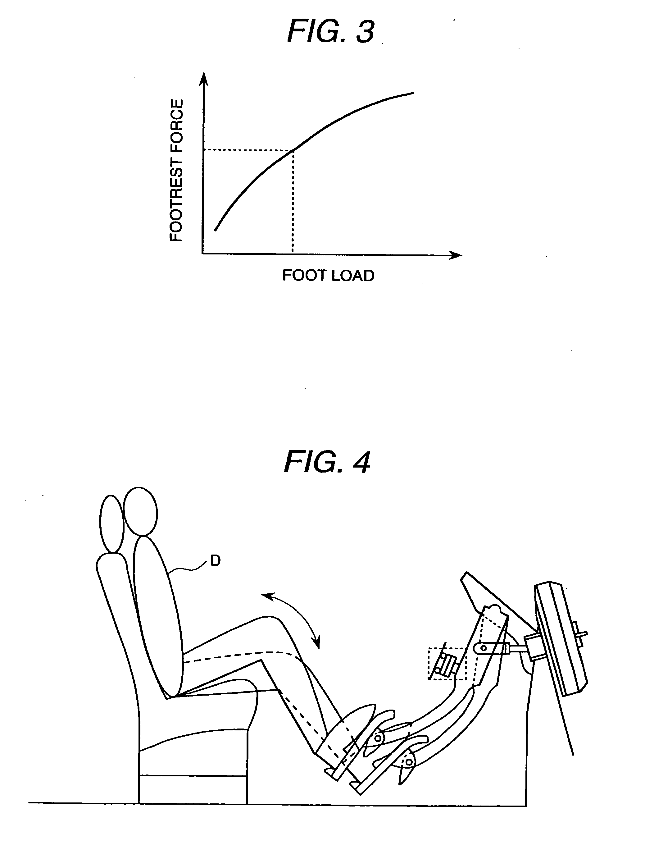
[0069] Further, FIG. 3 shows the relation between the foot load and the footrest force. Footrest force calculation means 16 increases the amount of the energizing to coil 13a so that the footrest force may increase by increasing o...
second embodiment
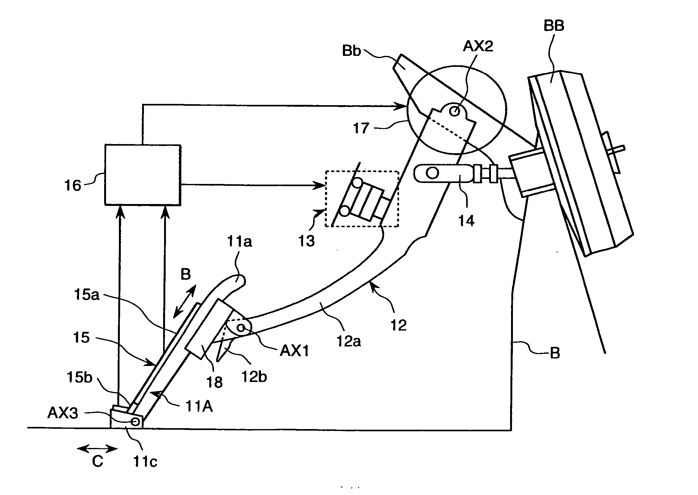
[0102]FIG. 8 is a plan view showing the configuration of the pedal member used for the pedal device of the vehicle according to the present invention. Further, FIG. 9 is side elevation of FIG. 8. In FIG. 8, the same sign as FIG. 7 shows the same part.
[0103] Slide member 11c is provided with rotatable support wheels 36a and 36b. Further, wheel 35a and 35b are provided in axis AX3. On the other hand, rail member 37, and wheel stoppers 38a, 38b, 38c and 38d are mounted on the floor face.
[0104] Wheels 35a, 35b, 36a and 36b are engaged with rail 37, and they are rotatable on rail 37.
[0105] As a result, slide member 11c can slide to the floor face.
[0106] Next, another sliding mechanism of the pedal member 11A is explained with reference to FIG. 10.
[0107]FIG. 10 is a side elevation showing another configuration of the pedal member used for the pedal device of the vehicle according to the second embodiment of the present invention. The same sign as FIG. 8 designates the same part.
[0108...
third embodiment
[0116] Next, the configuration of the pedal device of the vehicle according to the present invention and its operation are explained with reference to FIGS. 11-13. The configuration of the pedal device of the vehicle according to this embodiment is similar to one shown in FIG. 7. First, the sliding mechanism of the pedal member 11A is explained with reference to FIGS. 11 and 12.
[0117]FIG. 11 is a side elevation showing the configuration of the pedal member used for the pedal device of the vehicle according to the third embodiment of the present invention. FIG. 12 is a plan view of the configuration shown in FIG. 11. In FIGS. 11 and 12, the same sign as FIGS. 7 and 8 designates the same part.
[0118] Roller support members 40a, 40b, 40c and 40d to support rollers 39a, 39b, and belt member 41 are provided on the floor face. Slide member 11c is fixed to a part of belt member 41. Slide member 11c smoothly moves on the floor face because belt member 41 operates with the movement of slide ...
PUM
 Abstract
Description
Claims
Application Information
 - R&D
- Intellectual Property
- Life Sciences
- Materials
- Tech Scout
- Unparalleled Data Quality
- Higher Quality Content
- 60% Fewer Hallucinations
Browse by: Latest US Patents, China's latest patents, Technical Efficacy Thesaurus, Application Domain, Technology Topic, Popular Technical Reports.
© 2025 PatSnap. All rights reserved.Legal|Privacy policy|Modern Slavery Act Transparency Statement|Sitemap|About US| Contact US: help@patsnap.com


