
High-rise, fire-fighting, rescue and construction equipment

Inactive Publication Date: 2005-01-13
KORCHAGIN PAVEL V +4
View PDF10 Cites 18 Cited by
  • Summary
  • Abstract
  • Description
  • Claims
  • Application Information

AI Technical Summary

Benefits of technology

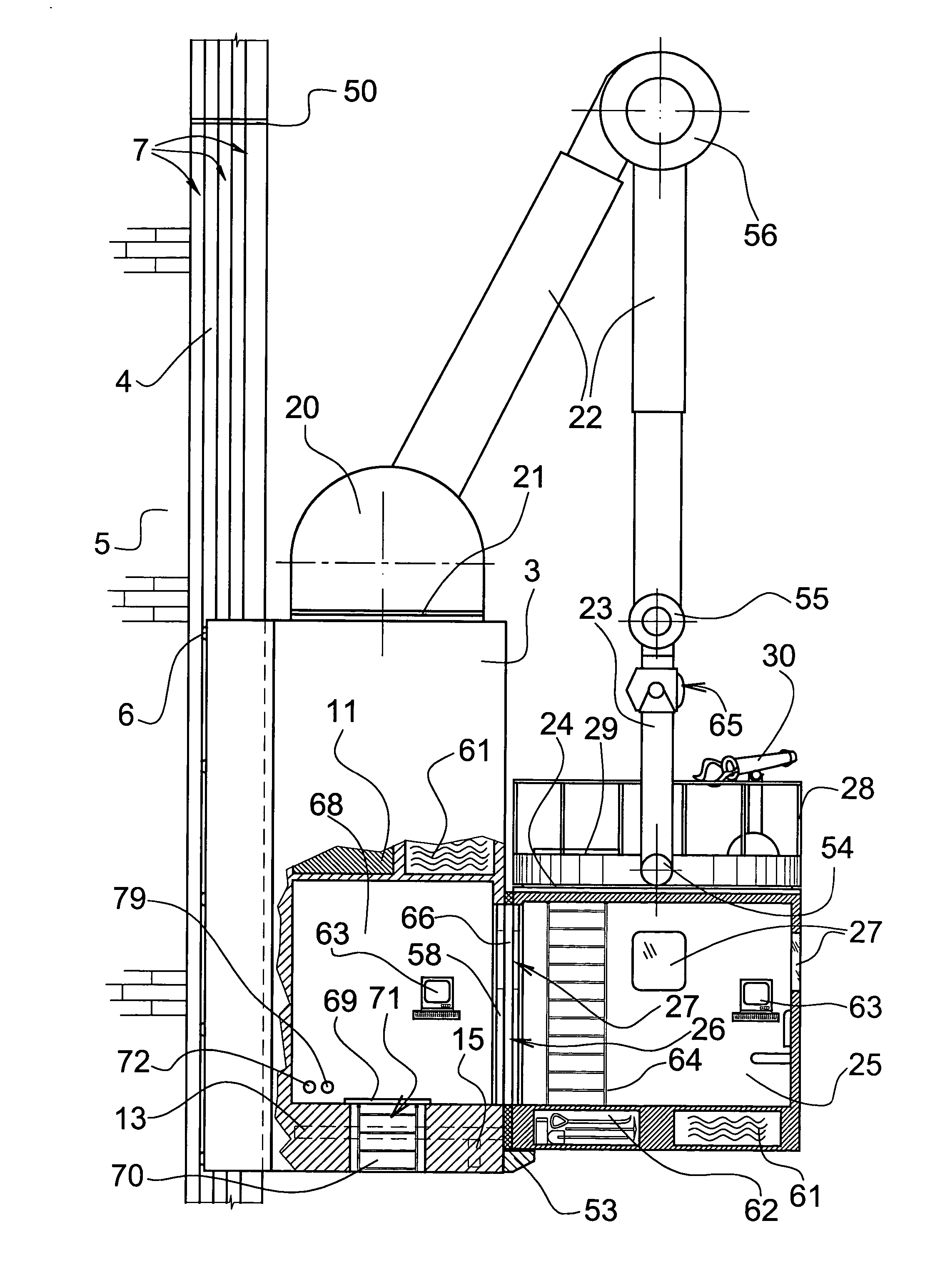
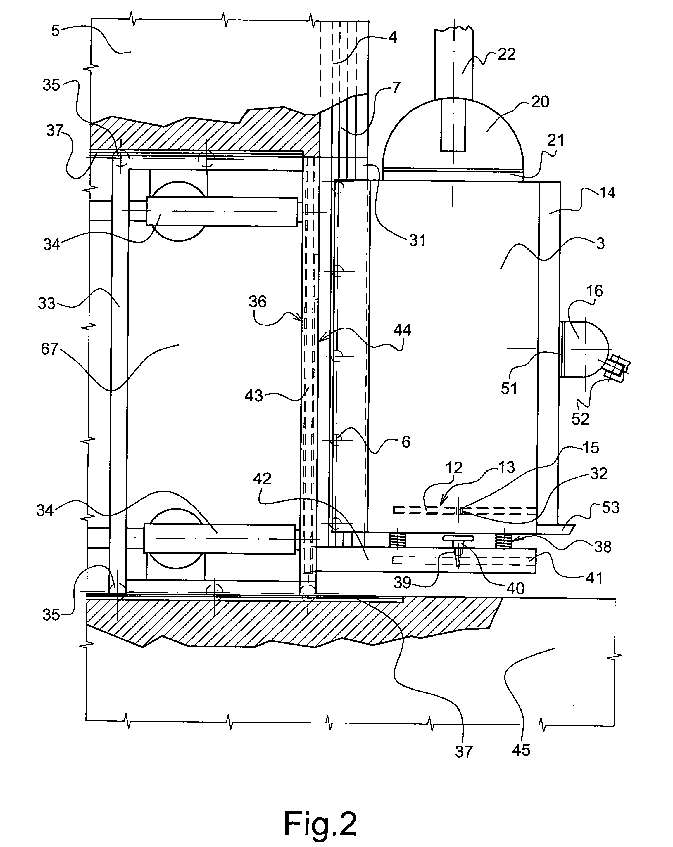
[0011] For safety purposes, the receiving panel is supplied with beveled guiding sides, and the mounting panel—with lower rounded corners; the lower part of the functional compartment has a concrete basis—for safe mounting-remounting operations; the auxiliary portion has a movable ladder—for safe transportation of people from the passenger compartment to the auxiliary portion.
[0013] It is an object of the invention to provide a functional compartment in a building; in this compartment a sliding frame is mounted, connected with jack mechanisms, which help the sliding frame move beyond the outer limits of a building and back. Safe and smooth sliding of the frame are ensured by supporting wheels inter-connected with guiders in the surfaces of the functional compartment.
[0018] It is an object of the invention to supply the auxiliary portion with a movable ladder—for safe transportation of people from the passenger section to the auxiliary portion.

Problems solved by technology

The prototype structure doesn't allow a completely mechanized installment of the attachable section of the H-shaped rail—to a building wall; and, to make a completely mechanized washing of building walls and windows (with the help of a cabin).

Method used


Image

  • High-rise, fire-fighting, rescue and construction equipment
  • High-rise, fire-fighting, rescue and construction equipment
  • High-rise, fire-fighting, rescue and construction equipment

Examples


Embodiment Construction

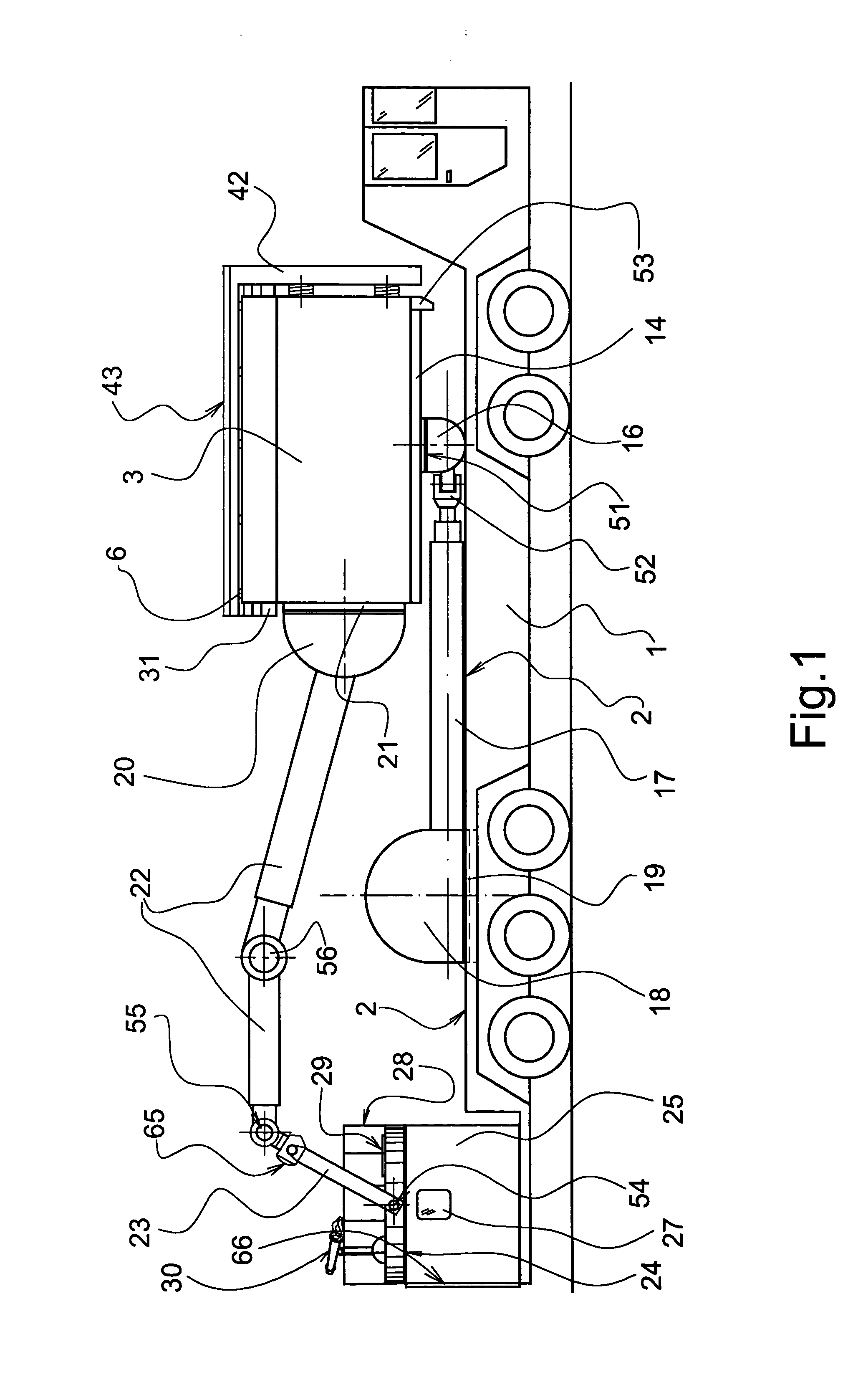
[0033] As it was explained and described in the previous application for the USA patent “High-Rise Fire-Fighting, Rescue and Construction Equipment” (Ser. No.—10 / 663,260, filing date—Sep. 16, 2003), the invention contained a device 30 and an elevator portion 31—for traveling vertically up and down on the outside of a building, and a crane portion—for extending an arm (telescopic) to a desired location on the building. The telescopic arm consists of two parts which are interconnected with the help of a pivoting mechanism. The telescopic arm has a pivot at its end attached to a cramp, with the help of a vertical rotating mechanism. The cramp, also, is pivoted, with the help of vertical rotating mechanisms, to an outside platform supplied with a barrier; a cabin is hanged onto the platform. The cabin itself can rotate 360 degrees around its vertical axis—with the help of a rotating mechanism. The cabin has inside a passenger compartment, with sliding doors—to ensure personnel's work an...


PUM


Abstract

An elevator system for traveling on a rail attached to the outside of a high-rise building. One elevator has a telescopic arm attached for reaching any position on or above the building. The telescopic arm consists of two parts, which are interconnected with a pivoting mechanism. The crane portion has a rotating mechanism and a pivoting mechanism for supporting one end of the arm. A functional compartment is provided in a building, a sliding frame is mounted in this compartment, connected with jack mechanisms; with the help of these mechanisms the sliding frame can slide beyond the outer limits of the building and back. Smooth and safe sliding of the frame is ensured by its supporting wheels sliding in guiding rails mounted in the surfaces of the functional compartment. The sliding frame is equipped in its front part, with a receiving panel with the right and left “pocket” guiders on it. The attachable section of the H-shaped rail is equipped with a mounting panel, wit the similar square structure as of the receiving panel. The thickness of the mounting panel is less than a clearance between the “pocket” guiders and the outer surface of the receiving panel. The receiving panel is supplied with beveled guiding sides, and the mounting panel—with lower rounded corners. The lower part of the functional compartment has a concrete basis. The auxiliary portion has a movable ladder. The back surface of the cabin is equipped with an attachable frame supplied with round mechanical brushes and a profile with holes for fluid sprayers and air routes. The frame is also equipped with fixing handles for mounting-demounting operations of the attachable frame.

Description

[0001] This application is a continuation-in-part of Ser. No. 10 / 663,260 filed on Sep. 16, 2003, which is a continuation-in-part of Ser. No. 10 / 431,946 filed on May 8, 2003, which is a continuation-in-part of Ser. No. 10 / 334,023 filed on Dec. 30, 2002, which is a continuation-in-part of Ser. No. 10 / 205,981 filed on Jul. 26, 2002.BACKGROUND OF THE INVENTION [0002] 1. Field of the Invention [0003] This invention relates to elevating facilities for high-rise buildings and, specifically—to combinations of elevator & crane systems running on a rail attached to the outside of a building. The facilities may have an elevator portion—for traveling vertically up and down, and a crane portion—to extend a telescopic arm to a desired location and to support a passenger cabin for rescue operations. The crane portion can also have a fire-fighting equipment—to access all parts of a building. The invention can be used for fire-fighting & rescue of people and equipment, and can also be used for const...

Claims


Application Information

Patent Timeline
IPC IPC(8): B66B9/187
CPCB66B9/187A62B1/02
Inventor KORCHAGIN, PAVEL V.KORCHAGINA, MARINA E.TIRSKAYA, SVETLANA E.BARARUSHKIN, VLADIMIR A.NIKITIN, VALERY I.KOSHEVAYA, ANNA V.ELISEEV, NIKOLAY N.
Owner KORCHAGIN PAVEL V
Learn More