Fluid dispenser head

a dispenser head and dispenser head technology, applied in the direction of rigid containers, pliable tubular containers, transportation and packaging, etc., can solve the problems of affecting the sealing effect and reducing the fixing quality, and achieve the effect of improving the sealing and fixing function

Active Publication Date: 2005-01-13
APTAR FRANCE SAS
View PDF11 Cites 5 Cited by
  • Summary
  • Abstract
  • Description
  • Claims
  • Application Information

AI Technical Summary

Benefits of technology

[0004] An object of the present invention is to define a dispenser head of that type that has improved sealing and fixing functions. In addition, the shutter and / or the body must be easy to mold and to remove from their molds. Permanent fixing is also another object. To achieve these objects, the present invention proposes, in one embodiment, for the fixing means to comprise at least one fixing profile facing radially outwards relative to the outlet axis X, and for the holding means to comprise at least one holding profile facing radially inwards towards the outlet axis X. This means that the shutter is fixed to the body over an outside periphery of the shutter and over an inside periphery of the body, unlike the fixing in the above-mentioned prior art dispenser head. According to another advantageous characteristic which may be implemented additionally or alternatively, the seal-receiving means are situated radially closer to the outlet axis X than the holding means. Advantageously, the seal-receiving means and the holding means extend substantially concentrically. This means that the fixing means are separated in space from the sealing means. In other words, the fixing means do not normally participate in sealing between the shutter and the body. Likewise, the sealing between the shutter and the body does not participate in fixing the shutter to the body. Thus, the sealing function and the fixing function are dissociated. It is thus possible to optimize each function (sealing and fixing) independently from each other. This does not apply to the prior art dispenser head in which the fixing participates in the sealing. Configuring the fixing profiles on the outside periphery of the shutter and separating the sealing function from the fixing function are two characteristics that can be implemented independently from each other.

Problems solved by technology

In which case, the shutter is removed from the mold by applying force, which often damages the fixing profiles.
The resulting fixing quality is lower.

Method used


Image

  • Fluid dispenser head
  • Fluid dispenser head
  • Fluid dispenser head

Examples


Embodiment Construction

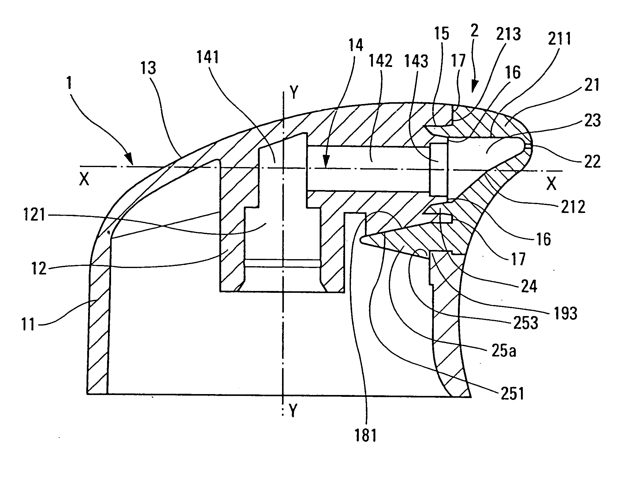
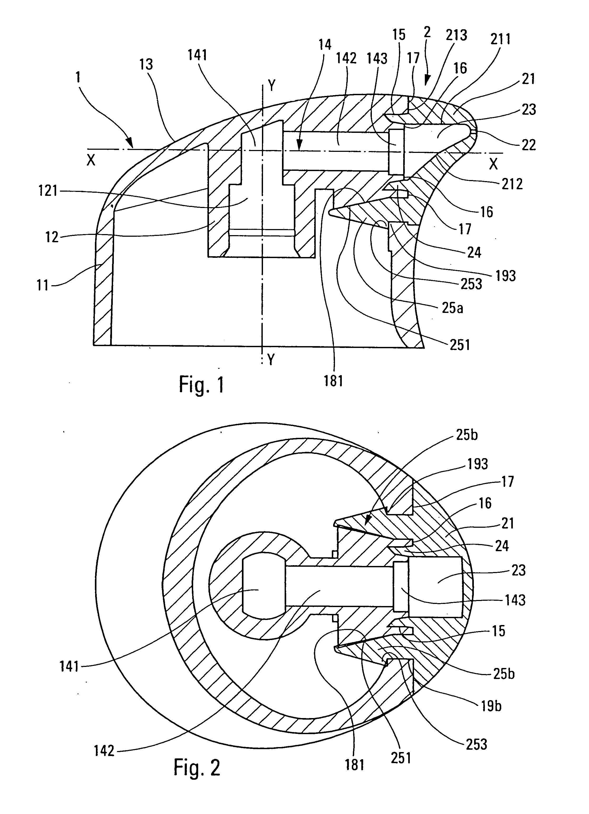
[0016] The dispenser head used to illustrate the present invention and shown in the figures is a dispenser head of the pusher type that can be pressed using one or more fingers in order to actuate a dispenser member, such as a pump or a valve, to which the head is fitted. However, a dispenser head of the present invention may be dissociated from the pusher function and have merely a discharging and dispensing function for discharging and dispensing the fluid. In which case, the pusher is separate from the head.

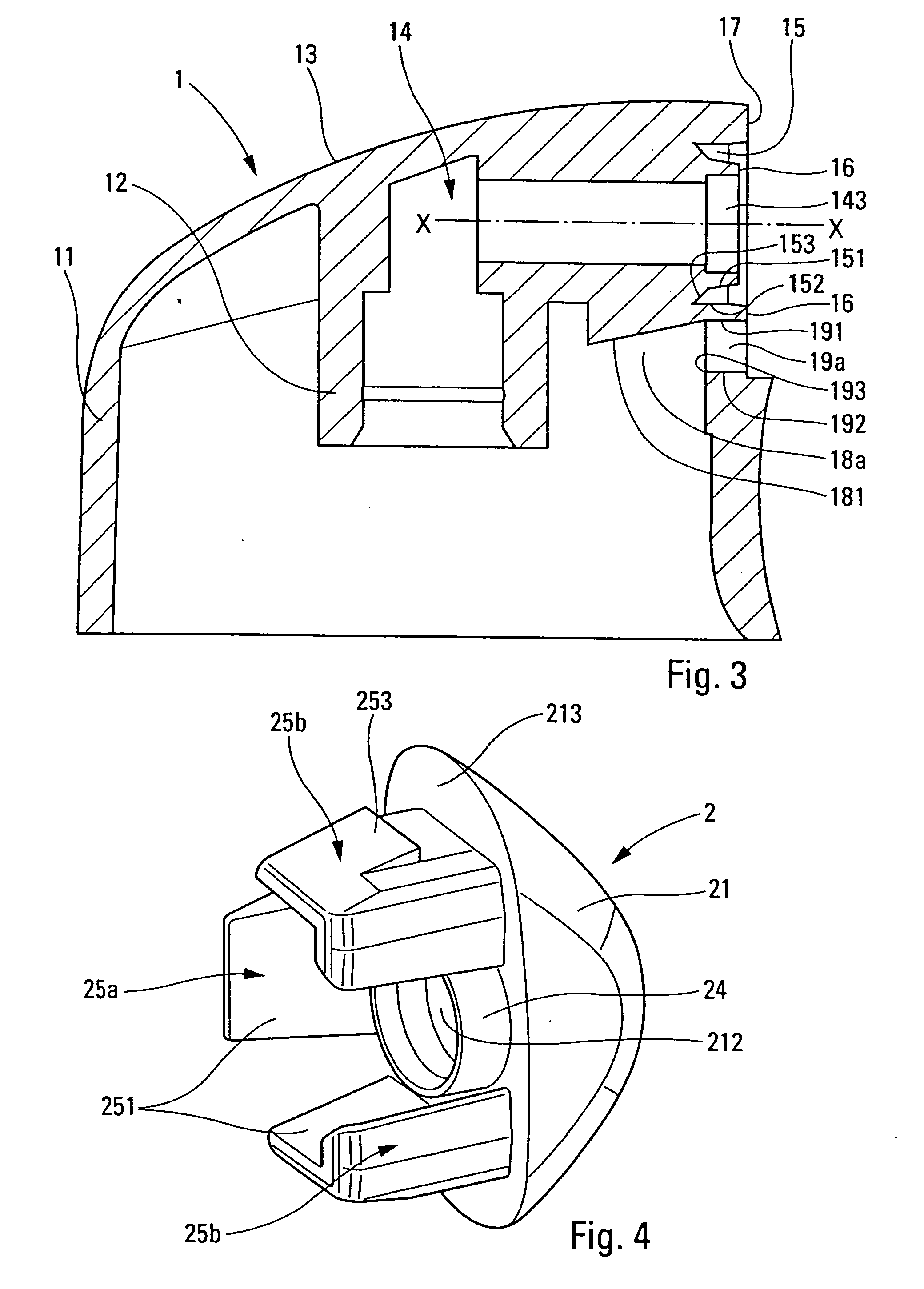
[0017] In the embodiment shown in the figures, the dispenser head is made up of two component elements, namely a body 1 and a shutter 2. The two elements may be made by injecting plastics materials into appropriate molds. The body is preferably made of a plastics material that is harder or stiffer than the shutter. For example, the shutter may be made of elastomer.

[0018] The body 1, which is preferably integrally molded in one piece, comprises a push top wall 13 which serves...


PUM


Abstract

A fluid dispenser head comprising a body (1) forming a dispensing duct (14) having an outlet (143) defining an outlet axis X, and a shutter (2) fitted to the body (1) for the purpose of selectively closing off the dispensing duct (14) at its outlet (143), the shutter forming a dispensing orifice (22) that is closed in the absence of fluid under pressure in the dispensing duct, said shutter being provided with sealing means (24) and with fixing means (25a) co-operating respectively with complementary seal-receiving means (15) and with complementary holding means formed by the body (1), the fixing means comprising at least one fixing profile (253) facing radially outwards relative to the outlet axis X, and the holding means comprising at least one holding profile (193) facing radially inwards towards the outlet axis X.

Description

CROSS REFERENCE TO RELATED APPLICATION [0001] This application claims the benefit under 35 U.S.C. §119(e) of pending U.S. provisional patent application Ser. No. 60 / 518,318, filed Nov. 10, 2003, and priority under 35 U.S.C. §119(a)-(d) of French patent application No. FR-03.08492, filed Jul. 10, 2003.TECHNICAL FIELD OF THE INVENTION [0002] The present invention relates to a fluid dispenser head designed to be fitted to a fluid dispenser member such as a pump or a valve. The dispenser head may form a pusher on which the user can exert pressure for the purpose of actuating the dispenser member. However, this pusher function may be dissociated from the dispenser head. Such a dispenser head may, in particular, be used in association with a dispenser member for being fitted to a fluid reservoir in the fields of perfumes, cosmetics, or indeed pharmaceuticals. BACKGROUND OF THE INVENTION [0003] The type of fluid dispenser head of the present invention comprises, in general, a body forming ...

Claims


Application Information

Patent Timeline
Patent Type & Authority Applications(United States)
IPC IPC(8): B65D83/16
CPCB65D83/20
Inventor GARCIA, FIRMINCORNET, GERARD
Owner APTAR FRANCE SAS
Why Eureka
Try Eureka