Semiconductor integrated circuit device

a technology of integrated circuit and semiconductor, applied in the direction of logic circuit coupling/interface arrangement, pulse technique, instruments, etc., can solve the problems of low processing speed of circuit, reduced circuit processing speed, and worst delay in high-speed operation

a technology of integrated circuit and semiconductor, applied in the direction of logic circuit coupling/interface arrangement, pulse technique, instruments, etc., can solve the problems of low processing speed of circuit, reduced circuit processing speed, and worst delay in high-speed operation

US20050007183A1Inactive Publication Date: 2005-01-13RENESAS ELECTRONICS CORP

Image

  • Semiconductor integrated circuit device
  • Semiconductor integrated circuit device
  • Semiconductor integrated circuit device

Examples


Embodiment Construction

[0108] Embodiments of the invention will be described hereinbelow with reference to the drawings.

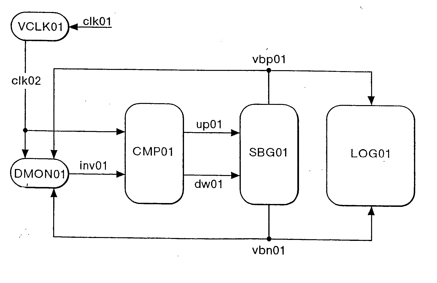
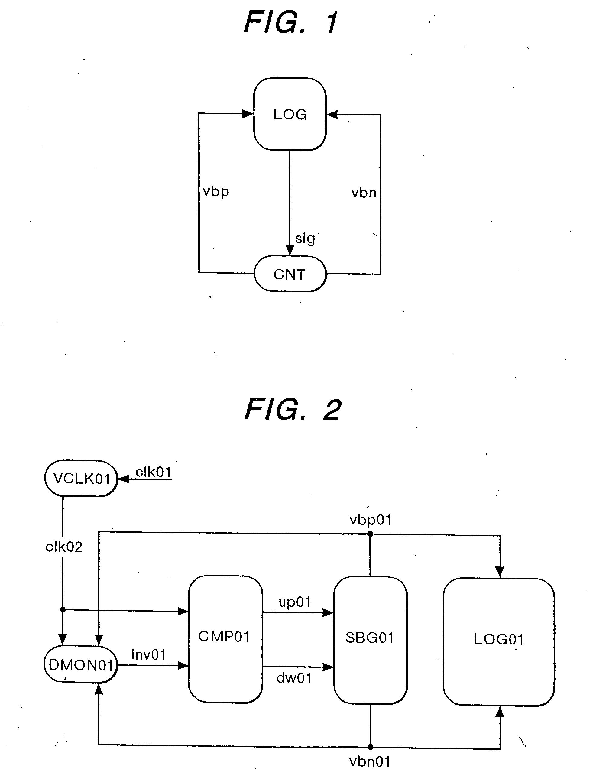
[0109]FIG. 1 is a diagram showing the fundamental concept of the invention. A main circuit LOG transmits a detected signal sig according to the operating speed of the circuit to a substrate-bias controller CNT. The substrate-bias controller CNT supplies both a substrate vias vbp for a p-channel type MOSFET and a substrate vias vbn for an n-channel type MOSFET to the main circuit LOG. The main circuit LOG is constructed by an MOS transistor. By controlling the substrate bias of the MOS transistor, a threshold voltage is controlled.

[0110] With such a construction, even when the characteristics of the MOS transistor fluctuate, due to variations in temperature and supply voltage or variations in the fabrication process of the MOS transistor, by controlling the substrate bias to control the threshold voltage of the MOS transistor, the operating speed can be made always constant. Further, th...


PUM


Abstract

A semiconductor integrated circuit device includes a logic circuit to perform a predetermined process, a clock generator to supply a clock signal to the logic circuit, and a speed controller to control the operation speed of the logic circuit. The clock generator changes the frequency of the clock signal by a frequency control signal during a time when the logic circuit is operating, and the speed controller controls the operating speed of the logic circuit in accordance with a change in the clock signal.

Description

[0001] This is a continuation-in-part application of patent application Ser. No. 08 / 622,389 (Mar. 27, 1996) in the United States and contains a part of that disclosure.TECHNICAL FIELD [0002] The present invention relates to a semiconductor integrated circuit, and, more particularly, a semiconductor integrated circuit device suitable for high-speed operation. BACKGROUND ART [0003] In an integrated circuit using CMOS transistors, characteristics fluctuation exists due to variations in transistor dimension caused by a fabrication process and a change in the environment, such as temperature or supply voltage, during operation. [0004] As described in “1994 symposium on VLSI technology digest of technical papers” (June, 1994), pp. 13 to 14, as an MOS transistor becomes finer, fluctuation in basic parameters, such as a threshold value due to the characteristics fluctuation caused by a fabrication process, becomes larger. [0005]FIG. 12 schematically shows delay of a CMOS circuit with respec...

Claims


Application Information

Patent Timeline
13 Jan 2005
Publication
US20050007183A1
IPC
H03K3/01; H03K19/003; H03K19/0185
CPC
H03K19/00323; H03K19/018585; H03K19/00384
Inventors
MIYAZAKI, MASAYUKI; ISHIBASHI, KOICHIRO