
Reflecting apparatus for backlight module of flat panel display

a technology of backlight module and reflector, which is applied in the field of reflectors, can solve the problems of low efficiency, excessive heat accumulation, scattered light during reflection, etc., and achieve the effect of increasing the efficiency of heat dissipation of the backlight module, preventing overheating of the light source, and increasing the intensity of reflected ligh

Active Publication Date: 2005-01-13
CPT TECH GRP
View PDF3 Cites 38 Cited by
  • Summary
  • Abstract
  • Description
  • Claims
  • Application Information

AI Technical Summary

Benefits of technology

[0007] An object of the present invention is to provide a reflecting apparatus, for reusing or collecting the scattered light to increase the intensity of reflected light, and to increase the efficiency of heat dissipation of the backlight module for preventing overheating of the light source.
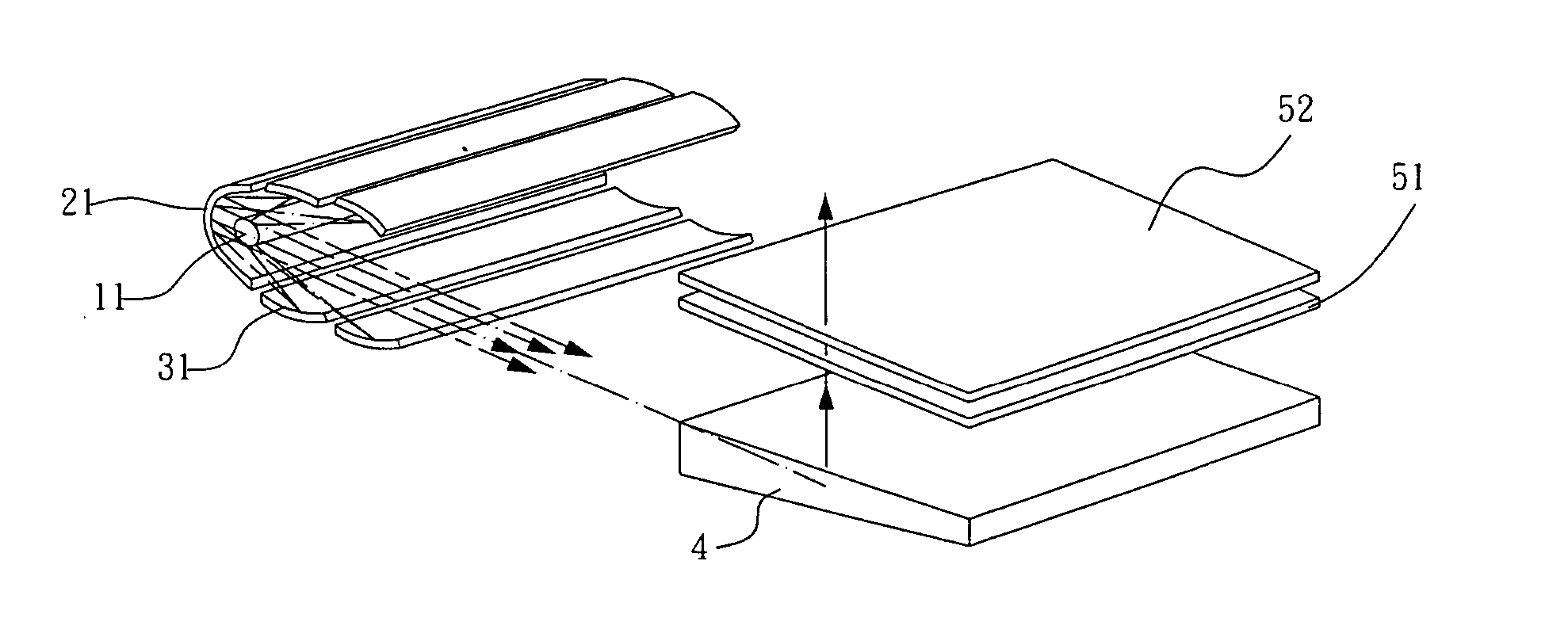
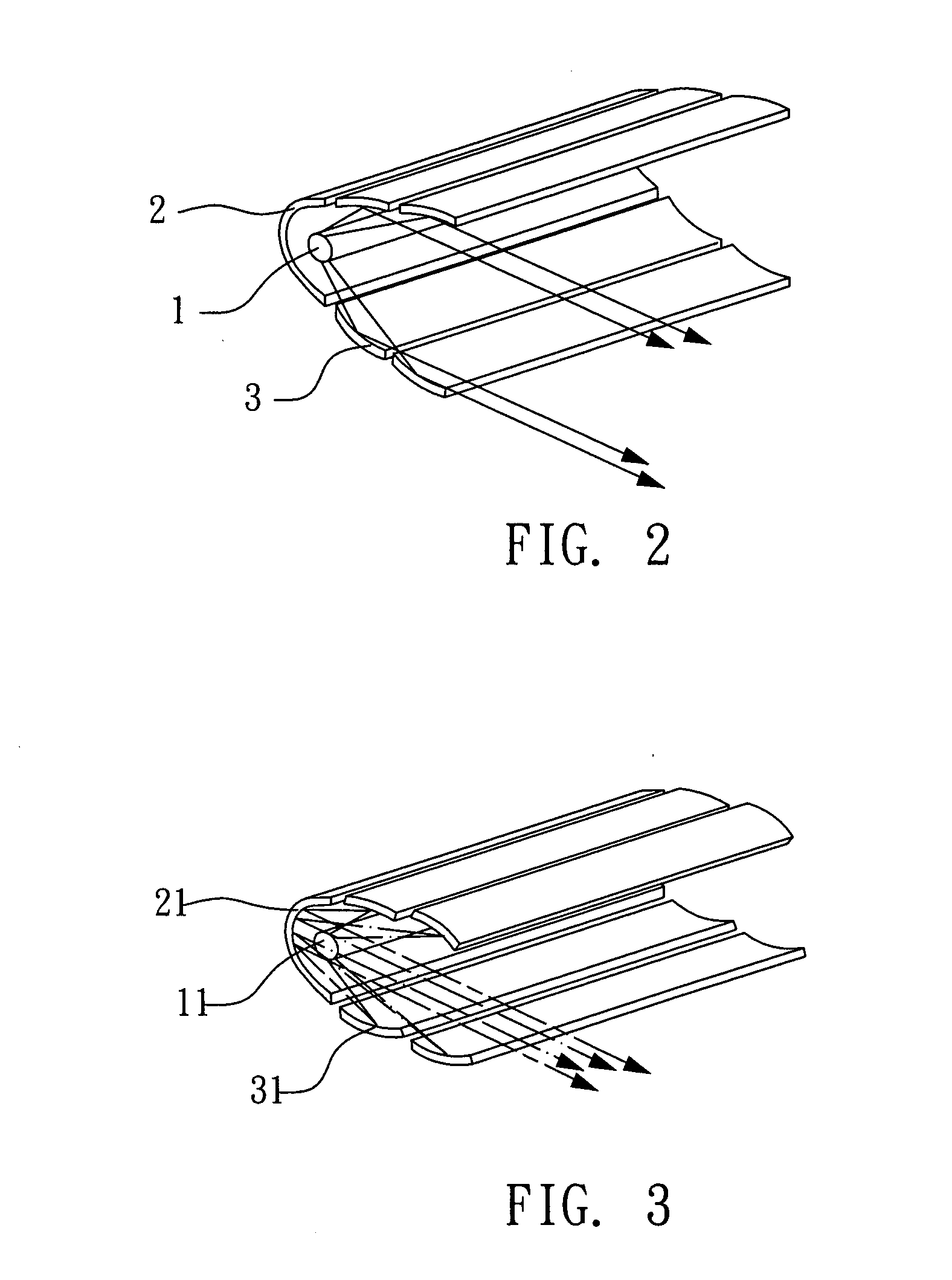
[0008] The reflecting apparatus of the present invention is mounted in a backlight module of a plane display. The backlight module includes a light guide distal from the reflecting apparatus, and a plurality of diffusers. The reflecting apparatus includes a light source; a reflector having a concave surface and a focus on the light source; and two substantially parallel sets of a plurality of partially overlapped light deflectors at one side of the reflector wherein a gap for ventilation exists between either two adjacent light deflectors of the same set or one light deflector and the reflector. A portion of light emitted from the light source is directed to the light guide after being reflected from the reflector, the remaining portion of light is directed to the light guide either after it has been deflected by the light deflectors or deflected by the light deflectors prior to being reflected by the reflector, and parallel light received at the light guide is deflected to the plane display as a backlight source of the plane display after passing the diffusers. By utilizing the present invention, intensity and brightness of light received at the light guide is significantly intensified without adversely consuming electrical energy.

Problems solved by technology

However, light is scattered and wasted during the reflection (i.e., low efficiency).
Further, heat may accumulate excessively due to poor ventilation of the well-known arrangement.
Also, the provision of additional light sources can consume electrical energy significantly.
Hence, the conventional backlight module is not satisfactory for users of large plane displays.

Method used


Image

  • Reflecting apparatus for backlight module of flat panel display
  • Reflecting apparatus for backlight module of flat panel display
  • Reflecting apparatus for backlight module of flat panel display

Examples


Embodiment Construction

[0016] With reference to FIGS. 2 and 4, there is shown a reflecting apparatus for the backlight module of a plane display constructed in accordance with a first preferred embodiment of the invention. As shown, the reflecting apparatus comprises a cylindrical light source 1, a reflector 2 having a concave surface and a focus on the light source 1, and two substantially parallel sets of a plurality of light deflectors 3 disposed at one side of the reflector 2. A portion of light emitted from the light source 1 is substantially parallel directed to a distal light guide (not shown) after reflecting from the reflector 2. The remaining portion of light is also directed to the distal light guide after it has been deflected by the light deflectors 3 in which deflected light is substantially parallel from the light deflectors 3 belonging to the same set. One light deflector 3 is partially overlapped by one or two adjacent light deflectors 3 of the same set for preventing light from escaping....


PUM


Abstract

A reflecting apparatus for a backlight module of a plane display is disclosed. The backlight module includes a light guide distal from the reflecting apparatus, and a plurality of diffusers. The apparatus comprises a light source, a reflector, and two substantially parallel sets of partially overlapped light deflectors wherein a gap exists between either two adjacent light deflectors of the same set or one light deflector and the reflector. A portion of emitted light is directed to the light guide after being reflected from the reflector. The remaining portion of light is directed to the light guide either after it has been deflected by the light deflectors or deflected by the light deflectors prior to being reflected by the reflector. Parallel light received at the light guide is deflected to the plane display as a backlight source of the plane display after passing the diffusers.

Description

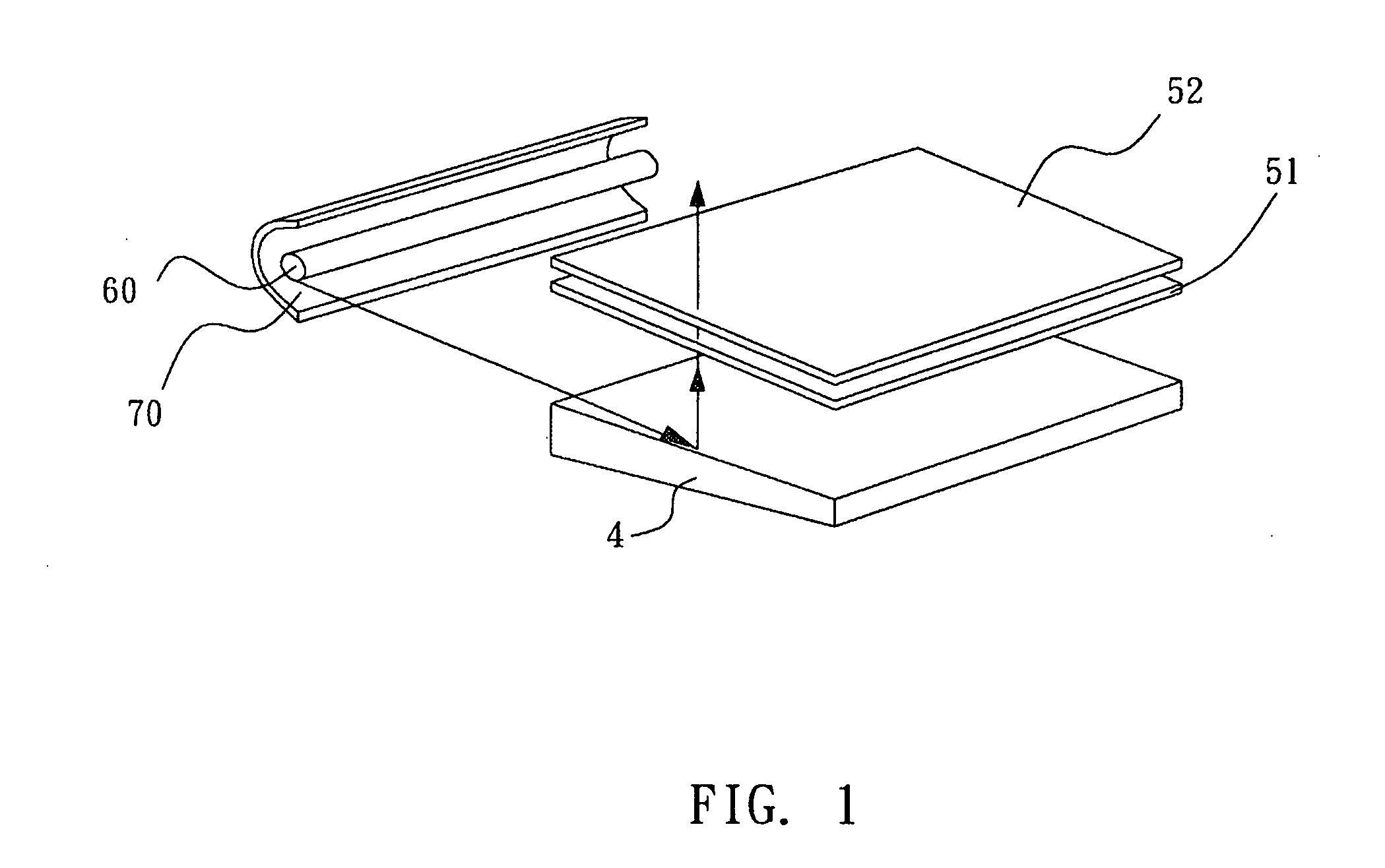
BACKGROUND OF THE INVENTION [0001] 1. Field of the Invention [0002] The present invention relates to reflectors and, more particularly, to a reflecting apparatus of the backlight module for a plane display with improved characteristics. [0003] 2. Description of Related Art [0004] Plane displays such as LCDs (liquid crystal displays), and the like have become the dominant type of displays in recent years due to their advantageous characteristics (e.g., lightweight, compactness, etc.) [0005] A backlight module is typically mounted in the plane display as the light source of the display. With reference to FIG. 1, there is shown a conventional backlight module comprising a light source 60, a light guide 4, two diffusers 51 and 52, and a reflector 70 having a concave surface. Light is emitted from the light source. Next, light is directed to the light guide 4 after being reflected by the reflector. Next, light is deflected to the display after passing the diffusers 51, 52. Increasingly l...

Claims


Application Information

Patent Timeline
Patent Type & Authority Applications(United States)
IPC IPC(8): F21V7/00F21V8/00G02B6/00
CPCF21V7/0025F21V7/005G02B6/0051F21Y2103/00G02B6/0031F21V7/09
Inventor YU, HONG-TIENWU, JIN-JEI
Owner CPT TECH GRP
Learn More