Speaker cabinet

a technology for cabinets and speakers, applied in the field of speakers, can solve the problems of low productivity, large-size forming machines, low-quality outer appearance of cabinets, etc., and achieve the effect of improving acoustic characteristics, high rigidity and shape stability

Active Publication Date: 2005-01-13
YAMAHA CORP
View PDF1 Cites 2 Cited by
  • Summary
  • Abstract
  • Description
  • Claims
  • Application Information

AI Technical Summary

Benefits of technology

[0009] In view of the foregoing, it is an object of the present invention to provide an improved speaker cabinet which has high rigidity and shape stability and can improve acoustic characteristics, and which can present a high-quality outer appearance with smooth surfaces without any undesired crease appearing on the surfaces of decorative plates due to bending of base members.

Problems solved by technology

However, the conventional curved-type cabinet board 1 of FIG. 5, where a plurality of the plywood boards 2a-2d are used as the base member 2, is disadvantageous in that it achieves only low productivity and needs a large-size forming machine, because it not only has to undergo a considerable number of adhesive applying steps but also has to be subjected to great curving pressure for a long time due to its high rigidity.
Consequently, the cabinet board 7 can not have a high-quality, smooth convexly curved outer surface, which would result in a low-quality outer appearance of the cabinet.
However, because a grain pattern is normally printed on the surface of the decorative sheet 3, the creases 10 would not be readily perceived visually and thus would be rarely recognized as significant defects.

Method used


Image

  • Speaker cabinet
  • Speaker cabinet
  • Speaker cabinet

Examples


Embodiment Construction

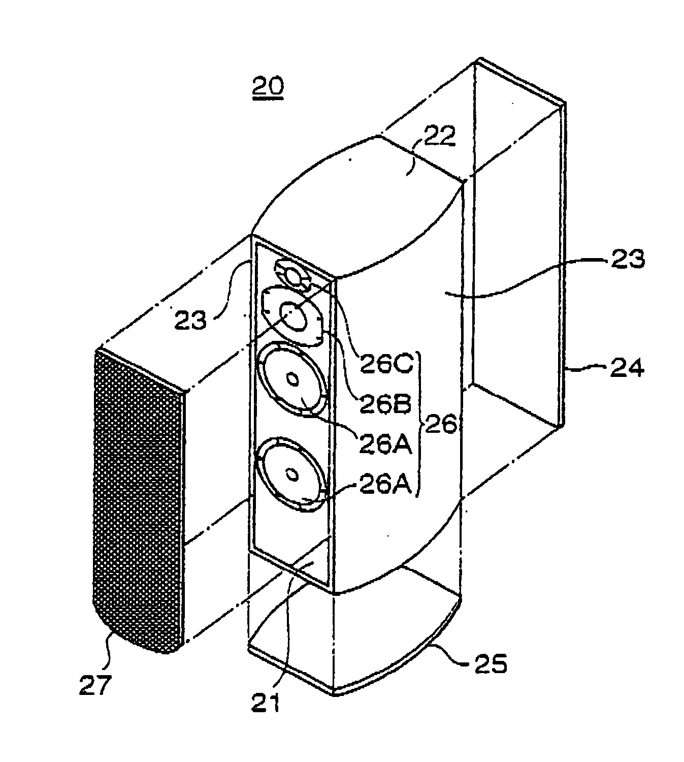
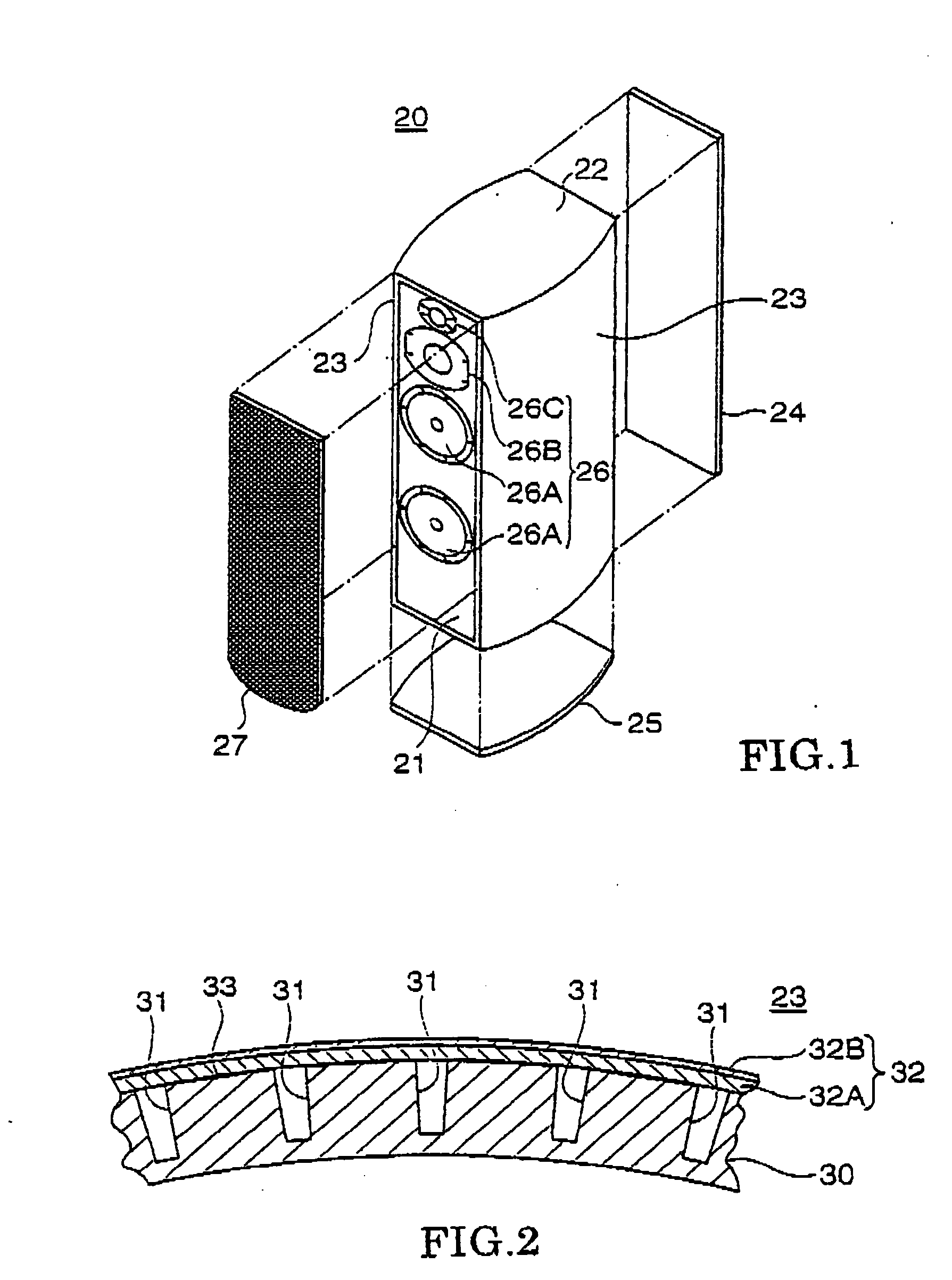
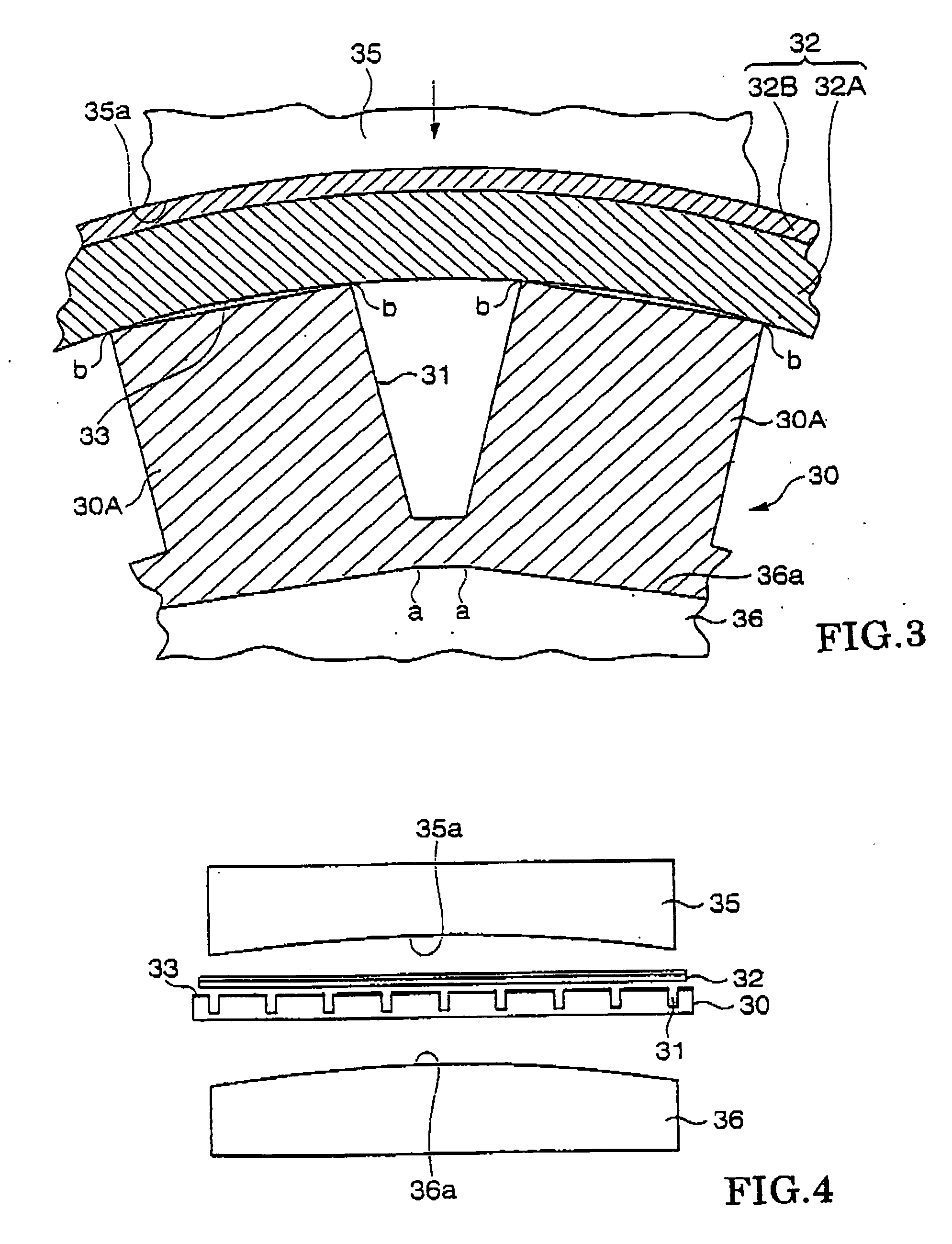
[0024]FIG. 1 is an exploded perspective view of a speaker cabinet in accordance with an embodiment of the present invention. FIG. 2 is a sectional view showing a principal section of a side plate employed in the speaker cabinet of FIG. 1, and FIG. 3 is an enlarged sectional view of the side plate.

[0025] In these figures, the speaker cabinet, generally represented by reference numeral 20, is in the shape of a vertically-elongated rectangular parallelepiped or box having six cabinet wall plates, i.e. a front plate 21. top plate 22, a pair of side plates 23, back plate 24 and bottom plate 25. To the front plate 21 are secured four speakers 26 of three different types and a grill net 27 covering the speakers 26. The four speakers 26 are two bass speakers 26A, one squawker speaker 26B and one tweeter speaker 26C.

[0026] Each of the front plate 21, top plate 22, side plates 23, back plate 24 and bottom plate 25 is formed by adhesively bonding a decorative sheet or plate to the outer surf...


PUM


Abstract

Side plates, constituting side surfaces of a speaker cabinet, each comprise a base member having a plurality of grooves formed in its outer surface (obverse surface) region at predetermined intervals, and a decorative plate adhesively bonded to the outer surface of the base member, in a laminated fashion, so as to cover the grooves. The laminated base member and decorative plate are pressed and curved, via upper and lower molds, so as to provide a smooth, convexlycurved outer surface. The grooves are adhesively bonded along their opening edges to the inner surface of the decorative plate, so that the opening edges of each of the grooves will not move toward or away from each other when external force is applied to the side plate.

Description

BACKGROUND OF THE INVENTION [0001] The present invention relates to speaker cabinets for audio equipment and the like. [0002] As outer walls of speaker cabinets, there have been employed cabinet boards typically made by adhesively bonding a decorative sheet or plate to the surface of a relatively heavy and hard base member, such as a plywood board, single-panel sheet (in this case, veneer sheet) or particle board, in a laminated fashion. The thus made cabinet board is cut into predetermined sizes and shapes to provide a front plate, left and right side plates, back plate and bottom plate, and these plates are jointed together at their edges to thereby provide a speaker cabinet having a rectangular parallelepiped shape. The speaker cabinet has a front covered with a grill net, and various kinds of speakers are accommodated in the interior of the speaker cabinet. Such speaker cabinets are disclosed, for example, in Japanese Patent Application Laid-open Publication Nos. HET-7-030987, H...

Claims


Application Information

Patent Timeline
Patent Type & Authority Applications(United States)
IPC IPC(8): H04R1/20H04R1/28H04R1/02H04R31/00
CPCH04R2209/027H04R1/2888
Inventor ITO, SHINYAMASHITA, SHINICHI
Owner YAMAHA CORP
Why Eureka
Try Eureka