Dynamic image decoding device

a dynamic image and decoding technology, applied in the field of dynamic image decoding devices, can solve the problems of large number of difference frames skipped in the rewind reproduced display, difficult for a user to retrieve a desired frame, and difficulty in producing smooth rewind reproduced display, etc., to achieve the effect of reducing the memory capacity of the buffer and reducing the number of difference frames previously stored in the buffer

Inactive Publication Date: 2005-01-13
PANASONIC CORP
View PDF4 Cites 33 Cited by
  • Summary
  • Abstract
  • Description
  • Claims
  • Application Information

AI Technical Summary

Benefits of technology

In the dynamic image decoding device, the decoding unit decodes a difference frame necessary for the output unit to output to the display device next (that is, a difference frame selected by the decoding unit and present between the third reference frame and the first reference frame) in parallel to the output of the frames from the output unit to the display device. Therefore, the number of difference frames previously stored in the buffer can be reduced as compared with the case where such parallel decoding is not performed.
In this manner, in the dynamic image decoding device, the memory capacity of the buffer can be reduced because the number of difference frames to be stored in the buffer is reduced.

Problems solved by technology

When the reference frames alone are displayed, however, difference frames present between the reference frames are skipped in the display, and hence, it is difficult to produce smooth rewind reproduced display.
Furthermore, in the case where the interval between the reference frames is long and a large number of difference frames are present between the reference frames, the number of difference frames skipped in the rewind reproduced display is so large that it is difficult for a user to retrieve a desired frame.

Method used


Image

  • Dynamic image decoding device
  • Dynamic image decoding device
  • Dynamic image decoding device

Examples


embodiment 1

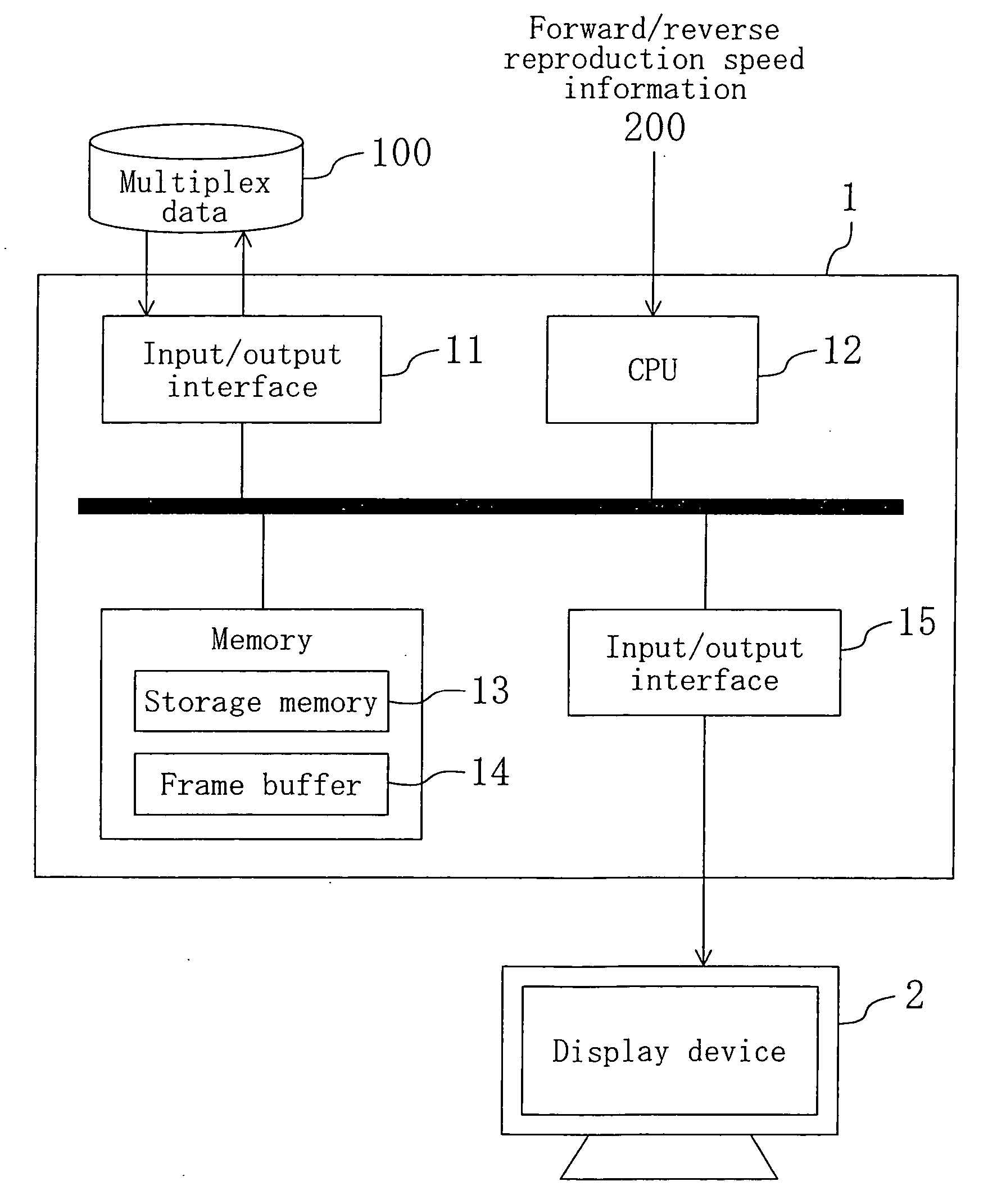
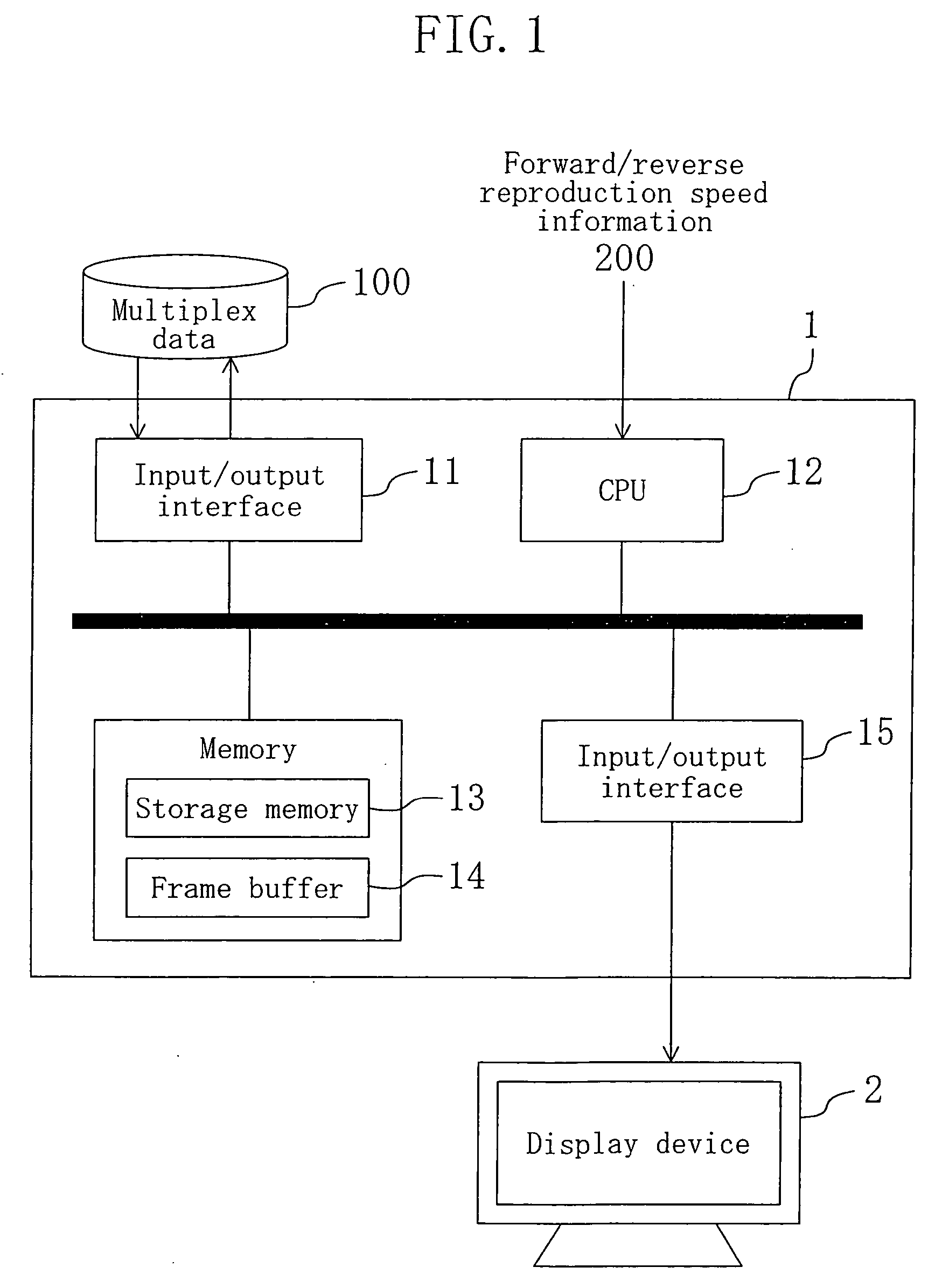
The whole architecture of a dynamic image reproducing system according to Embodiment 1 is shown in FIG. 1. This system performs reproducing processing (ordinary reproducing and special reproducing processing) for encoded dynamic image data included in multiplex data 100. This system includes a dynamic image decoding device 1 and a display device 2. The dynamic image decoding device 1 includes input / output interfaces 11 and 15, a CPU 12, a storage memory 13 and a frame buffer 14.

The input / output interface 11 performs input processing for the multiplex data 100 externally supplied.

The CPU 12 analyzes the multiplex data, acquires frame information, decodes encoded dynamic image data and controls the whole system in accordance with forward / reverse reproduction speed information 200. The forward / reverse reproduction speed information 200 corresponds to a reproducing direction and a reproduction speed specified by a user.

The storage memory 13 stores the multiplex data 100, the fram...

embodiment 2

The whole architecture of a dynamic image reproducing system according to Embodiment 2 is the same as that shown in FIG. 1 but this dynamic image reproducing system is different from that of Embodiment 1 in the operation of the CPU 12.

Now, ordinary reproducing processing performed in the dynamic image reproducing system of Embodiment 2 will be described with reference to FIGS. 13 and 14.

[Ordinary Reproducing Processing]

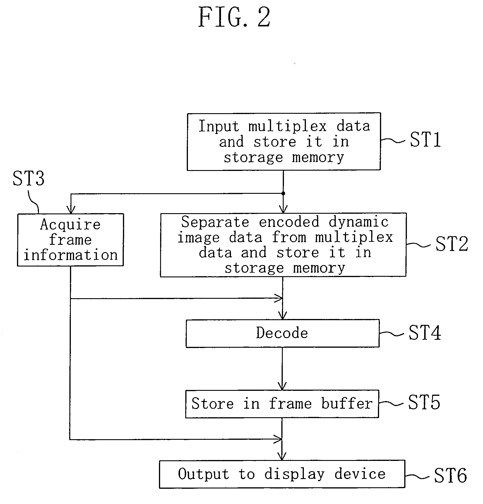
[Steps ST1 through ST5]

The procedures of steps ST1 through ST5 of the ordinary reproducing processing are performed in the same manner as in Embodiment 1 so as to store decoded dynamic image data (frame data) in the frame buffer 14.

[Steps ST3 and ST1 through ST15]

Also, the procedures of step ST3 and steps ST11 through ST15 that performed in the rewind reproducing processing in Embodiment 1 are performed so as to select a difference frame Px.

[Step ST21]

Next, the CPU 12 makes the difference frame Px, which is selected in step ST15, remain in the frame buffe...

embodiment 3

The whole architecture of a dynamic image reproducing system according to Embodiment 3 is the same as that shown in FIG. 1, but this dynamic image reproducing system is different from that of Embodiment 1 in the operation of the CPU 12. Also, in Embodiment 3, on the basis of a difference frame stored in the frame buffer in the rewind reproducing processing of Embodiment 2, another difference frame is decoded.

Now, the ordinary reproducing processing performed in the dynamic image reproducing system of Embodiment 3 will be described with reference to FIGS. 13 and 18.

[Ordinary Reproducing Processing]

The same procedures as those of Embodiment 2 are performed so as to store the decoded data of a difference frame Px in the frame buffer 14 in step ST21.

Next, the rewind reproducing processing performed in the dynamic image reproducing system of Embodiment 3 will be described with reference to FIGS. 17 and 18.

[Rewind Reproducing Processing]

[Steps ST1 and ST2]

First, the procedures...


PUM


Abstract

A dynamic image decoding device of the invention is a device for decoding encoded dynamic image data. The dynamic image decoding device has an ordinary reproducing mode and a rewind reproducing mode. The dynamic image decoding device includes an analysis unit, a decoding unit and an output unit. The analysis unit selects at least one of a plurality of difference frames. The decoding unit decodes the difference frame selected by the analysis unit, a first reference frame and a second reference frame. The output unit outputs, to a display device, the difference frame, the first reference frame and the second reference frame having been decoded by the decoding unit successively in the order from one present more ahead on the time axis, namely, in the order of the second reference frame, the difference frame and the first reference frame, on the basis of frame information in the rewind reproducing mode.

Description

BACKGROUND OF THE INVENTION The present invention relates to a device for decoding encoded dynamic image data, and more particularly, it relates to control of rewind reproducing processing for encoded dynamic image data. Today, owing to development of information technology, voice and dynamic images (video) compressed and stored in a storage medium in accordance with the MPEG standard or the like can be reproduced for amusement. The MPEG standard is an encoding standard for encoding dynamic image data as a reference frame and a difference frame. In a dynamic image decoding device for decoding and displaying the encoded dynamic image data having such a data structure, in order that a user can easily and rapidly retrieve contents, it is significant to support special reproducing processing such as fast-forward and rewind in accordance with an instruction made by the user. For dynamic image compressed in accordance with the MPEG standard, a dynamic image decoding device capable of co...

Claims


Application Information

Patent Timeline
Patent Type & Authority Applications(United States)
IPC IPC(8): H04N5/76H04N5/783H04N5/92H04N9/804H04N19/423H04N19/44H04N19/50H04N19/503H04N19/593
CPCH04N9/8042H04N5/783
Inventor NISHIMURA, KENGOYAGI, YORIKOMATSUMOTO, MICHIHIROMOROHASHI, TAKAHARU
Owner PANASONIC CORP
Why Eureka
Try Eureka