
Eureka
For R&D, Eureka makes reading and utilizing patents & technical documents easy.
Eureka AIR
Designed for self-driven R&D workflows. Generate viable solutions, solve complex R&D challenges, empower your innovation with AI.

Eureka Materials
Designed for material experts only. Revolutionize your material R&D, from search, analyze, to developing new materials.

TechResearch
Generate reliable direction feasibility study reports for your R&D in just a few steps.

TechSeek
Discover and master advanced knowledge NOW. Basics, ideas, possibilities, all at once.

TechMind
As an expert in R&D Theories, TechMind can generates customized viable solutions instantly.

TechRisk
Analyze your overall solution with one click, know your potential R&D risks in advance.

TechMonitor
Get weekly tech updates, stay abreast of the latest tech innovations and key insights.
Fusing system and temperature control method thereof for use in an image forming apparatus
- Summary
- Abstract
- Description
- Claims
- Application Information
AI Technical Summary
Benefits of technology
Problems solved by technology
Method used
Image

Examples
embodiment 1
[0059]FIG. 6 is a block diagram illustrating a fusing system 100 according to a first embodiment of the present invention, which is applied to an electrophotographic image forming apparatus such as a laser printer, a copier, a FAX and the like.
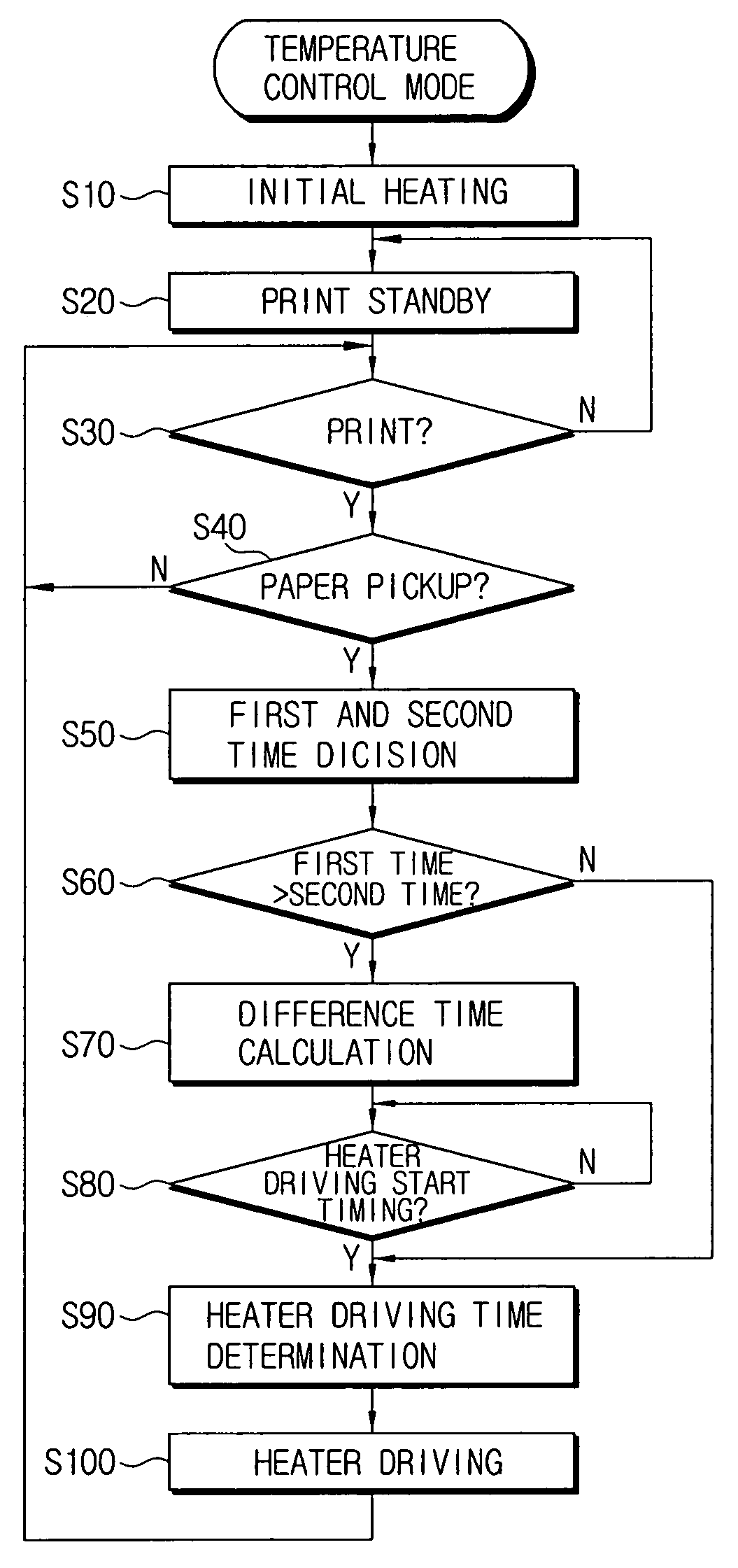
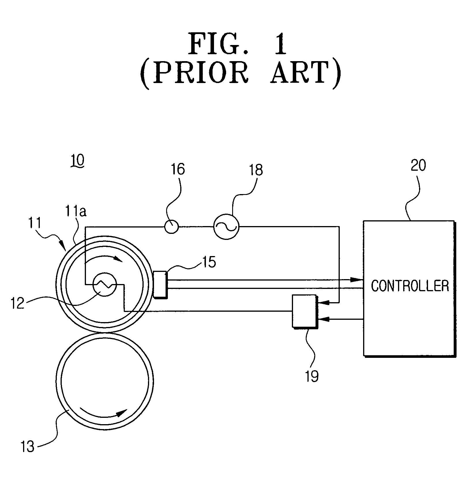
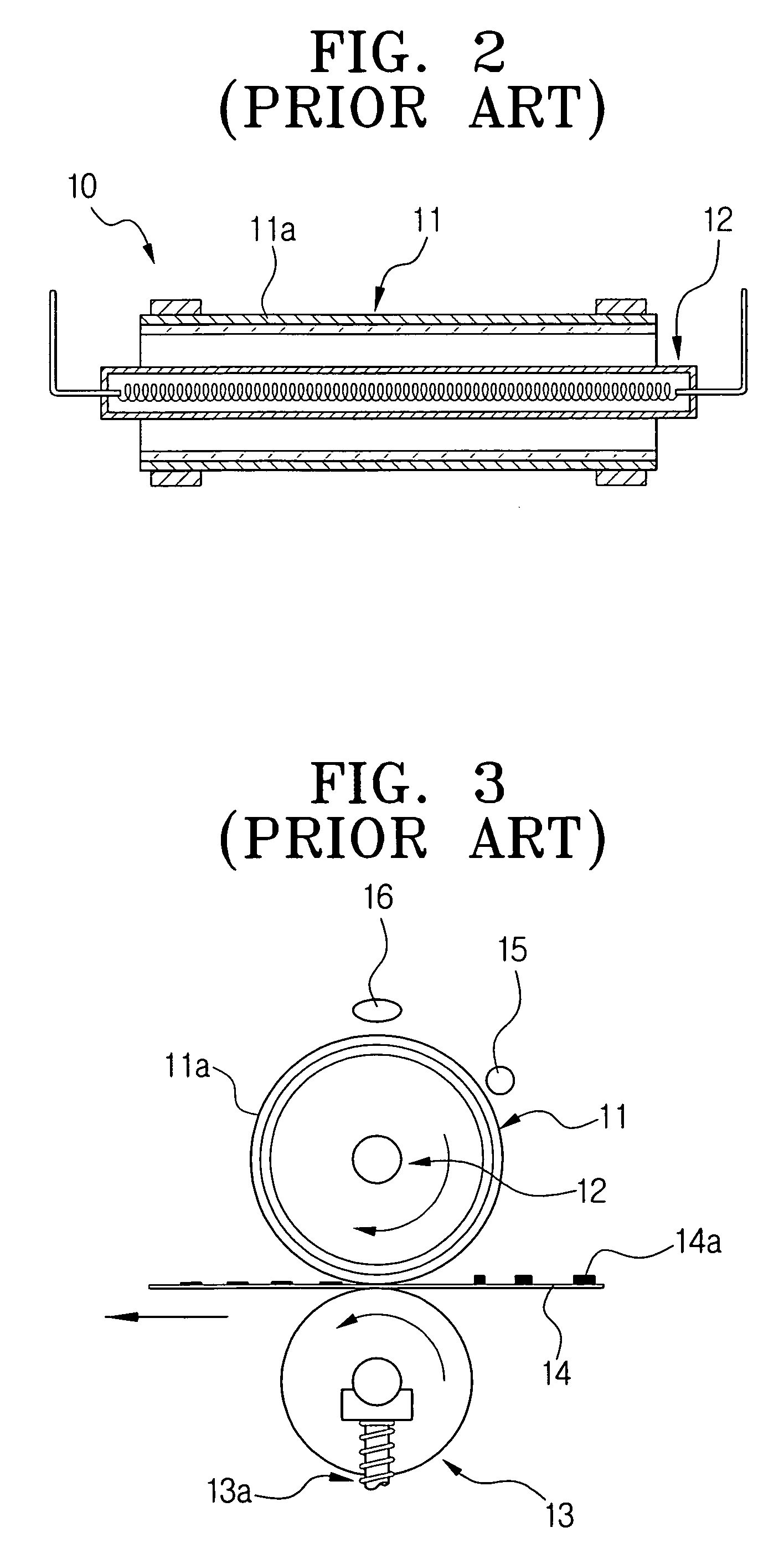
[0060] The fusing system 100 includes a fusing unit 101 for fusing a toner image transferred onto a sheet of printing paper (not shown) with heat and pressure to affix it thereon and having a fusing roller 111 with a heater 112, and a fusing temperature control unit 102 determining a driving-start timing and a driving time th of the heater 112 of the fusing unit 101 for a paper supply and controlling the heater 112 to drive for the decided driving time th, to coincide a point of time when the sheet of printing paper arrives at the fusing roller 111 with a point of time when a heat of the preheated heater 112 reaches a surface of the fusing roller 111. The fusing unit 101 is provided with a fusing roller 111 formed of an aluminum cylinder havi...
embodiment 2
[0088]FIG. 8 is a block diagram illustrating a fusing system 100′ according to a second embodiment of the present invention, which is applied to an electrophotographic image forming apparatus such as a laser printer, a copier, a FAX and the like.
[0089] The fusing system 100′ includes a fusing unit 101 fusing toner image transferred on a sheet of printing paper (not shown) with a heat and a pressure to affix it thereon and having a fusing roller 111 with a heater 112, and a fusing temperature control unit 102′ for determining a driving start timing and a driving time th of the heater 112 of the fusing unit 101 for a period of paper supply and controlling to drive the heater 112 for the determined driving time th.
[0090] The description about the fusing unit 101 will be omitted here, as it is identical to that of the conventional fusing unit described with reference to FIG. 6.
[0091] The fusing temperature control unit 102′ is provided with a paper feeding part 130′ having a pickup r...
PUM
 Abstract
Description
Claims
Application Information
 - R&D Engineer
- R&D Manager
- IP Professional
- Industry Leading Data Capabilities
- Powerful AI technology
- Patent DNA Extraction
Browse by: Latest US Patents, China's latest patents, Technical Efficacy Thesaurus, Application Domain, Technology Topic, Popular Technical Reports.
© 2024 PatSnap. All rights reserved.Legal|Privacy policy|Modern Slavery Act Transparency Statement|Sitemap|About US| Contact US: help@patsnap.com