
Excavation tooth installation assembly and method

a technology for installing assembly and excavation teeth, which is applied in the direction of soil-shifting machines/dredgers, construction, etc., can solve the problems of tooth loss, tooth is no longer serviceable, and has to be replaced, so as to limit upward movement of pins

Inactive Publication Date: 2005-01-20
DUKE ALAN
View PDF6 Cites 16 Cited by
  • Summary
  • Abstract
  • Description
  • Claims
  • Application Information

AI Technical Summary

Benefits of technology

"The invention provides an improved solid pin for securing excavation teeth in a fixed position upon an adapter carried by an excavation bucket. The solid pin is constructed to avoid loosening due to wear of the rubbery material sandwiched between the steel members in prior art pins. The tooth assembly method includes the use of a solid pin that can be easily installed by insertion through a lower base portion of the teeth and through a vertical opening extending upwardly through the adapter. The solid pin is securely fastened to the tooth base with a lock nut on the threaded shank within an opening in the thickened area. The invention also provides an engaging stop surface to limit upward movement of the pins as they are inserted through the assembly. The teeth are tapered forward to match the inclination of the pins. The retaining pin comprises a stop member and a threaded nipple for engagement by a lock nut, and opposed surfaces are provided on the teeth to aid in engaging the stop member against going completely through the assembly and against rotation of the pins in the upright passageway."

Problems solved by technology

As the tooth is used often, sometimes in elevated temperature environments, the constant pressure on the pin causes the rubber-like substance to weaken so that the pin then falls out through the bottom of the tooth and adaptor installation assembly resulting in the loss of the tooth.
After suitable hydraulic mechanism is repeatedly used to load the bucket with soil or rock, there is a resulting movement of the pin, resulting in ware so that the tooth is no longer serviceable and has to be replaced.

Method used


Image

  • Excavation tooth installation assembly and method
  • Excavation tooth installation assembly and method
  • Excavation tooth installation assembly and method

Examples


Embodiment Construction

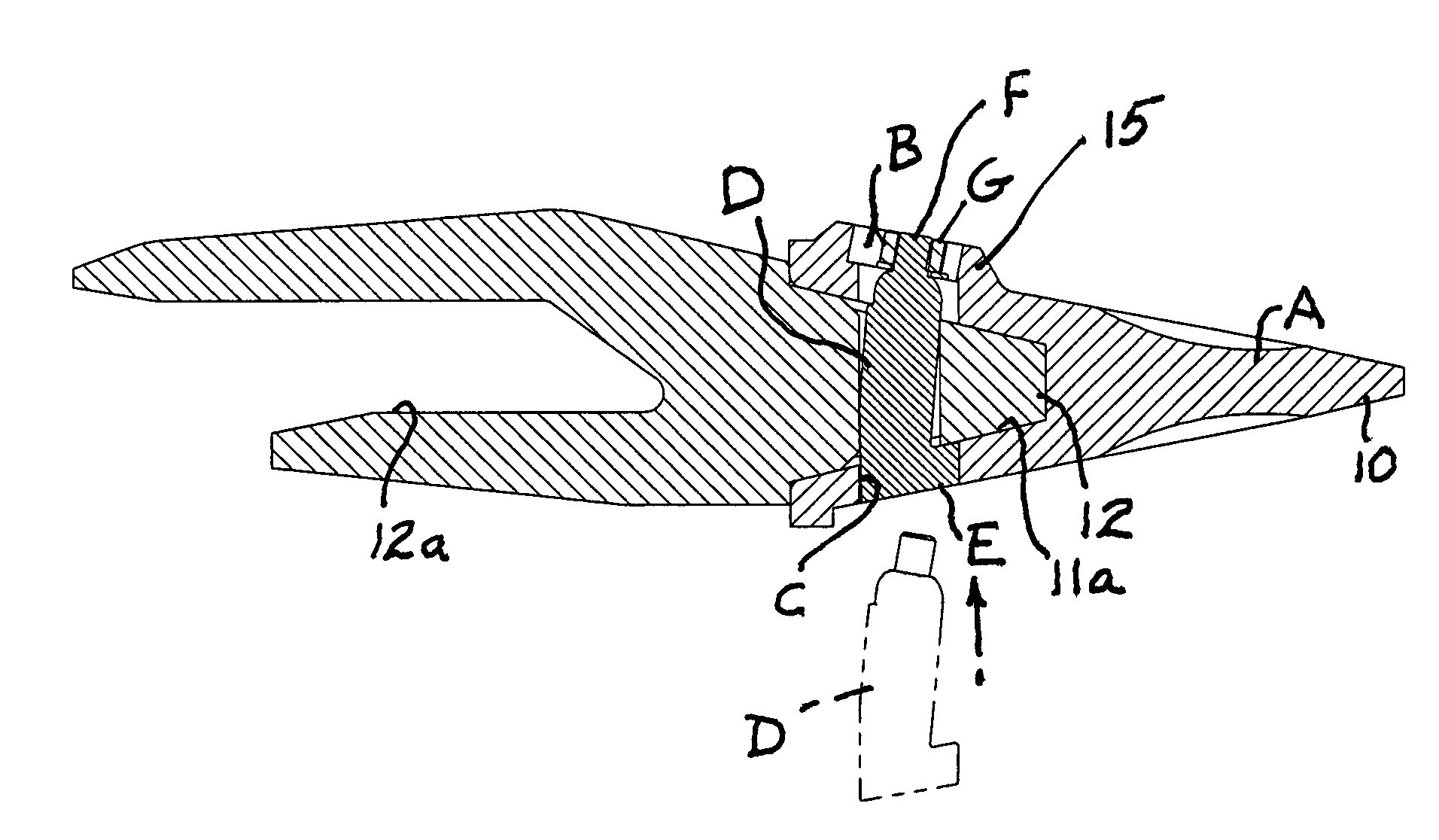
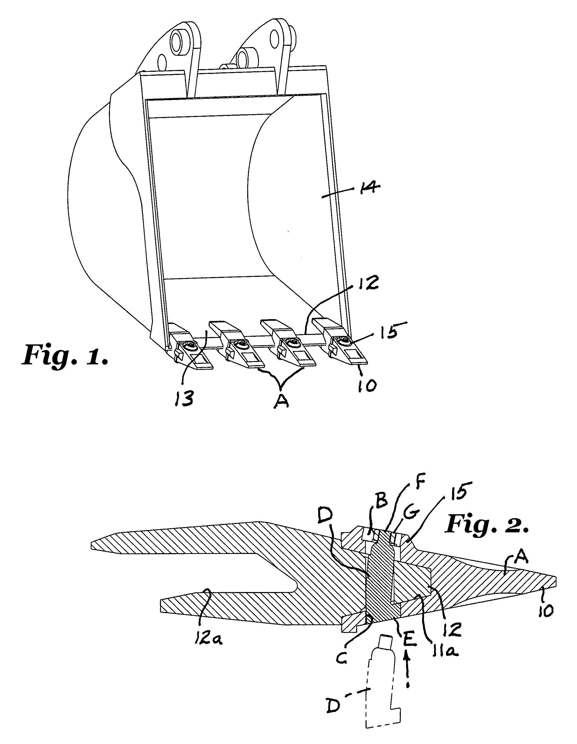
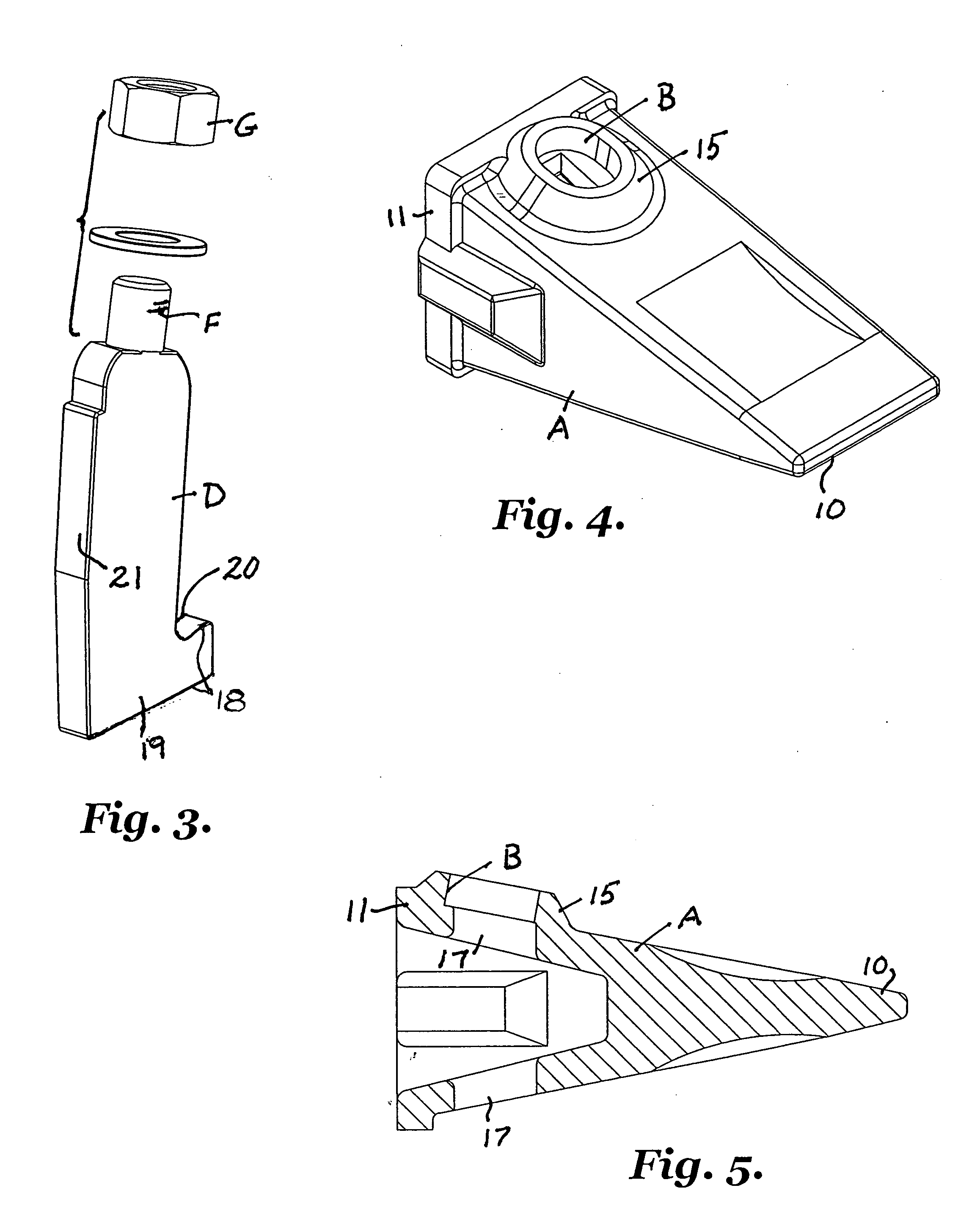
[0024] The drawings illustrate an excavation tooth and fastener assembly and method of excavation installing teeth on an adapter secured to a leading edge of an earth-moving implement. An excavation tooth A has a tooth point on one end and a tooth base at the other end configured for reception upon the adapter. An upper recess B in the tooth base is accessible from an exterior of the tooth base. A lower recess C in the tooth base opposite the upper recess is also accessible from an exterior of the tooth base.

[0025] An elongated retaining pin D has a stop member E to limit the extent to which the pin enters a vertical opening in the adapter during installation. An upright threaded shank F carried by one end of the retaining pin is configured for engagement by a compatible fastener G so that, after the retaining pin is inserted through the adapter into the upper and lower recesses in the tooth base and secured by the fastener, a new tooth is fixed upon the adapter.

[0026] The method ...


PUM


Abstract

A solid steel retaining pin (D) has a stop member (E) on a lower end for limiting the extent to which the pin is moved upwardly through the recess (C) into the excavation teeth (A) and adapter during installation. An upper recess (B) is defined by a thickened conical upper surface of the bases of the teeth to protect the bolts (G) carried by upwardly extending shanks (F) during digging.

Description

BACKGROUND OF THE INVENTION [0001] This invention relates to the securement of excavation teeth upon the shank, more commonly referred to as the adapter, welded to the steel lip of a backhoe bucket and the like. [0002] In accordance with the prior art, excavation teeth are secured to the adapter utilizing an elongated vertical steel pin having a rubbery center section forming a sandwich. The pin is driven through a vertical opening or passageway in a base portion of the tooth and a forward projection of the adaptor. [0003] The rubbery center section is formed by a suitable deformable resilient material such as neoprene so that when the pin is driven into the vertical opening the pin presses against the walls of the adapter after insertion. As the tooth is used often, sometimes in elevated temperature environments, the constant pressure on the pin causes the rubber-like substance to weaken so that the pin then falls out through the bottom of the tooth and adaptor installation assembl...

Claims


Application Information

Patent Timeline
Patent Type & Authority Applications(United States)
IPC IPC(8): E02F9/28
CPCE02F9/2833
Inventor DUKE, ALAN
Owner DUKE ALAN
Learn More