Exhaust heat utilizing refrigeration system

a technology of exhaust heat and refrigeration system, which is applied in the direction of domestic cooling apparatus, lighting and heating apparatus, machine operation mode, etc., can solve the problems of increasing not only the initial cost, but also the running cost, and the coefficient of performance remarkably reduced

Inactive Publication Date: 2005-01-20
SANYO ELECTRIC CO LTD
View PDF12 Cites 24 Cited by
  • Summary
  • Abstract
  • Description
  • Claims
  • Application Information

AI Technical Summary

Benefits of technology

[0006] The present invention is characterized by comprising a heat pump apparatus equipped a compressor, a first heat exchanger, a pressure-reducing device and a second heat exchanger, and an absorption type refrigerating machine equipped with a regenerator using exhaust heat as a heat source, a condenser, an evaporator and an absorber, wherein a third heat exchanger is connected to the first heat exchanger in parallel, and a heat source of the third heat exchanger is achieved from the evaporator of the absorption type refrigerating machine.

Problems solved by technology

When they are of air-cooling type, sufficient evaporating temperature cannot be achieved in an evaporator disposed outdoors under heating operation at a low outside temperature, so that there is a problem that COP (Coefficient of Performance) is remarkably reduced.
However, both the cases need heat source equipment, which increases not only the initial cost, but also the running cost because a burner or the like needs combustion heat of fossil fuel.

Method used


Image

  • Exhaust heat utilizing refrigeration system
  • Exhaust heat utilizing refrigeration system
  • Exhaust heat utilizing refrigeration system

Examples


Embodiment Construction

[0022] Embodiments of the present invention will be described with reference to the accompanying drawings.

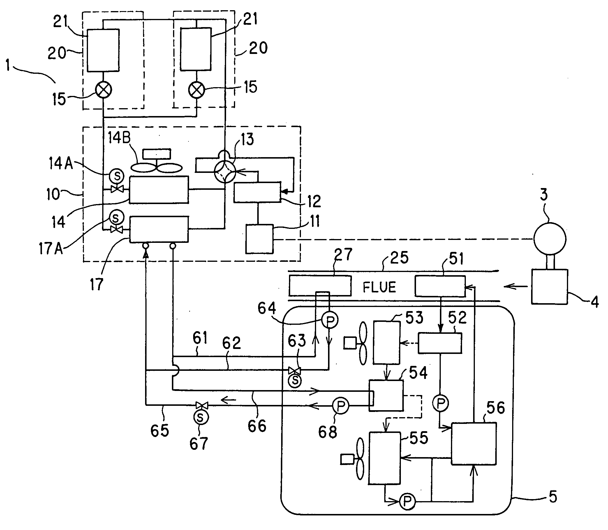
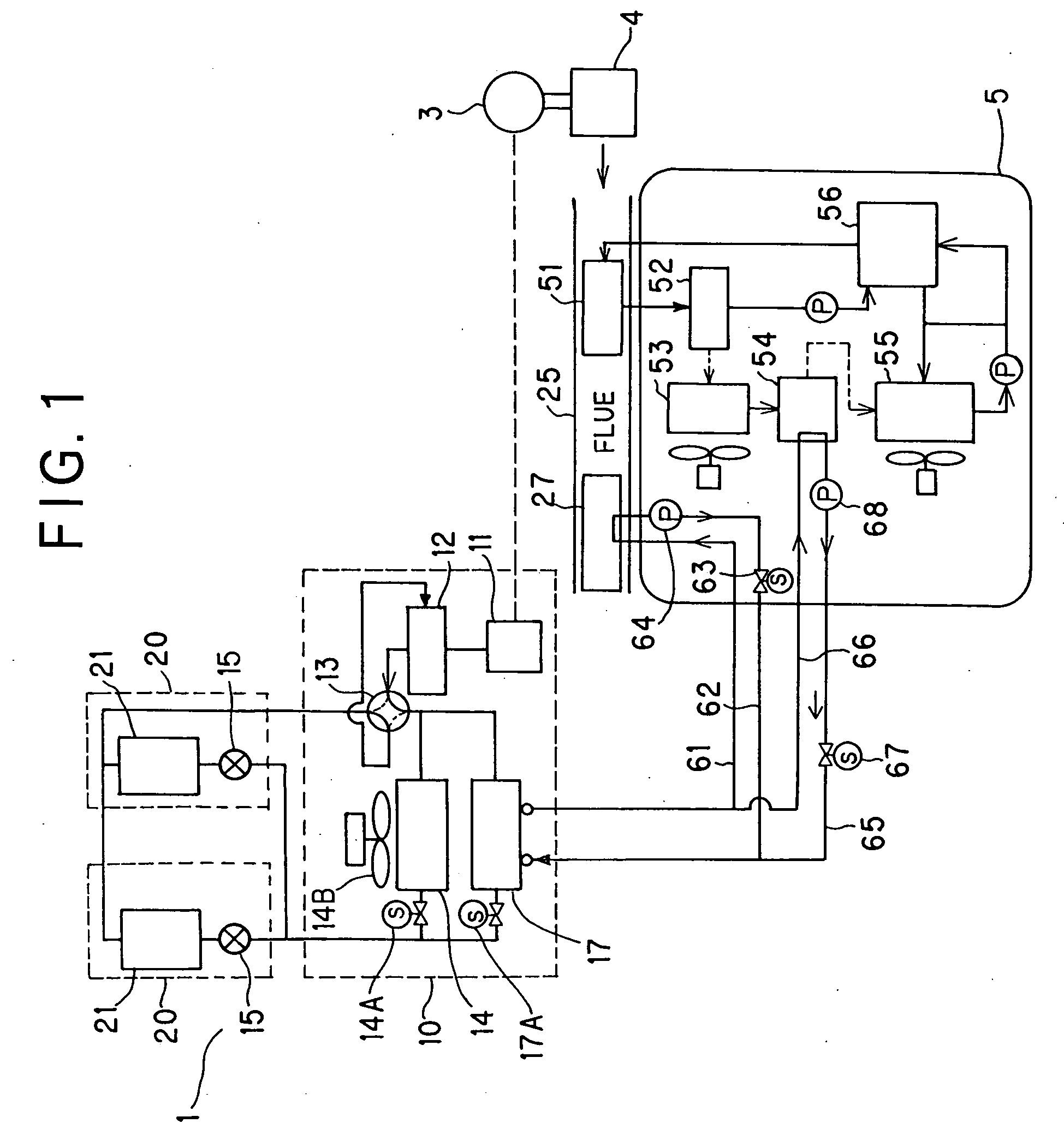
[0023]FIG. 1 is a circuit diagram showing an exhaust-heat using refrigerating system. In FIG. 1, 1 represents an air conditioner (heat pump apparatus), 3 represents an electric generator, 4 represents a micro gas turbine for driving the electric generator 3 and 5 represents an absorption type refrigerating machine.

[0024] The air conditioner 1 comprises an outdoor unit 10 and indoor units 20. In the outdoor unit 10 are mounted a motor 11 connected to the electric generator 3, a compressor 12 driven by the motor 11, a four-way valve 13 and an air-cooling type heat exchanger (first heat exchanger) 14 having a fan 14B. In the indoor unit 20 are mounted a pressure-reducing device 15 and an air cooling type heat exchanger (second heat exchanger) 21.

[0025] In FIG. 1, the motor 11 and the compressor 12 are illustrated as being independent of each other, however, they may be mounted i...


PUM


Abstract

There is provided an exhaust-heat using refrigerating system which can add the function of refrigerant heater, condenser or super-cooler by using exhaust heat. The system comprises a heat pump apparatus 1 equipped with a compressor 12, a first heat exchanger 14, a pressure-reducing device 15 and a second heat exchanger 21, and an absorption type refrigerating machine 5 equipped with a regenerator 51 using exhaust heat as a heat source, a condenser 53, an evaporator 54 and an absorber 55. A third heat exchanger 17 is connected to the first heat exchanger 14 in parallel, and the heat source of the third heat exchanger 17 is achieved from the evaporator 54 of the absorption type refrigerating machine.

Description

TECHNICAL FIELD [0001] The present invention relates to an exhaust heat using refrigerating system suitably used for a show case, an air conditioner or the like. BACKGROUND ART [0002] There is generally known an air conditioner comprising a heat pump apparatus having a compressor, a condenser, a pressure-reducing device and an evaporator. [0003] In this type of air conditioner, the evaporator and the condenser are frequently designed to be of air-cooling type. When they are of air-cooling type, sufficient evaporating temperature cannot be achieved in an evaporator disposed outdoors under heating operation at a low outside temperature, so that there is a problem that COP (Coefficient of Performance) is remarkably reduced. In order to solve this problem, there has been hitherto proposed an air condition in which a refrigerant heater such as a burner or the like is disposed and COP is increased by heating refrigerant. Furthermore, there has been also proposed another air conditioner in...

Claims


Application Information

Patent Timeline
Patent Type & Authority Applications(United States)
IPC IPC(8): F25B13/00F25B25/02F25B27/02
CPCF25B13/00F25B27/02F25B25/02Y02P80/15Y02A30/274
Inventor SAWADA, NORIOMATSUMOTO, KAZUO
Owner SANYO ELECTRIC CO LTD
Why Eureka
Try Eureka