Precious stone cut and method of making

a precious stone and cut technology, applied in the field of cutting precious stones, can solve the problems of requiring extraordinary loss of rough diamond material, limited ability to significantly return white light, and loss of light through the bottom of the diamond to create dead zones, etc., and achieve the effect of increasing scintillation, brilliance, and dispersion of ligh

Inactive Publication Date: 2005-01-20
SO DAVID
View PDF49 Cites 36 Cited by
  • Summary
  • Abstract
  • Description
  • Claims
  • Application Information

AI Technical Summary

Benefits of technology

[0007] The present invention provides a stone cut and a method for cutting a stone providing increased scintillation, brilliance, and dispersion of light. The cut, in accordance with one aspect of the invention, has a girdle, crown, and pavilion, and includes an increased number of facets on either or both the crown or the pavilion over the traditional number facets. The increased number of facets may be obtained by providing additional upper girdle facets (over the traditional number) surrounding the perimeter of the stone above the girdle. According to an embodiment, the upper girdle facets preferably extend from a lower side along the girdle of the stone to a common upper vertex located toward a table on the crown. Preferably, there are three upper girdle facets per side of the table.

Problems solved by technology

The traditional round brilliant cut model, due its unique faceting arrangements, has limited ability to return white light significantly.
The loss of light through the bottom of the diamond creates dead zones.
Furthermore, due to the light return and internal light flow efficiencies of the round brilliant cut model, the proportions that are necessary for this model to achieve optimal light performance requires extraordinary loss of rough diamond material during the cutting process.
Although, at the optimal light performance level for the traditional model, the diamond appears more impressive than the poorly cut diamonds, the magnitude and quality of brilliance, dispersion and scintillation that a round shape diamond cut is capable of achieving is not maximized.
Nonetheless, the current desire of many cutters to cut diamonds to the ideal cut proportions of the traditional round brilliant cut is discouraged by the requirements of significant weight loss of the rough diamond material.

Method used


Image

  • Precious stone cut and method of making
  • Precious stone cut and method of making
  • Precious stone cut and method of making

Examples


Embodiment Construction

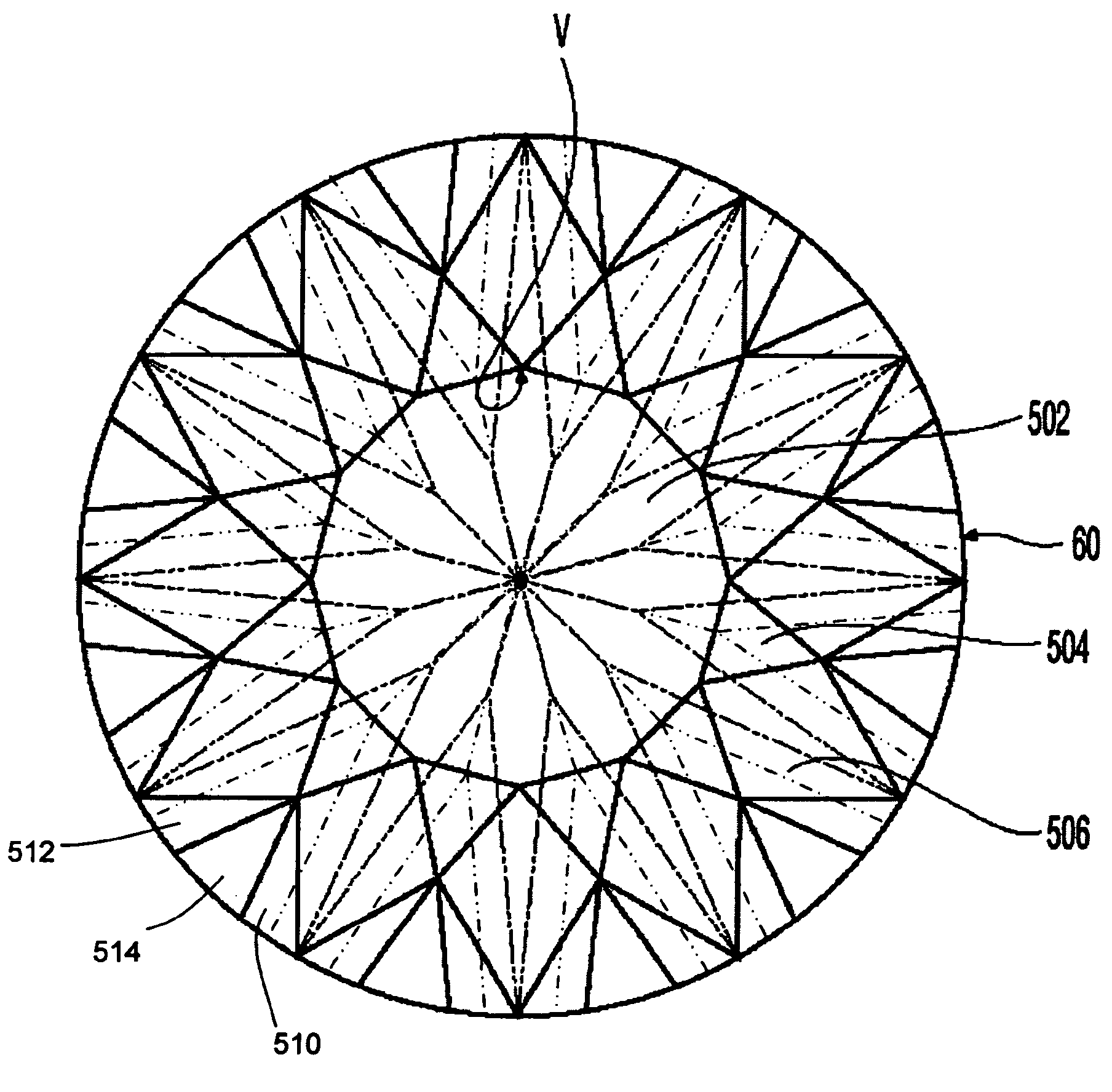
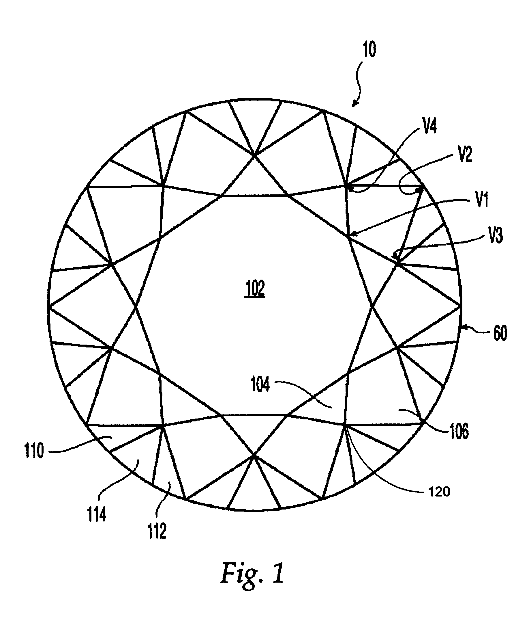
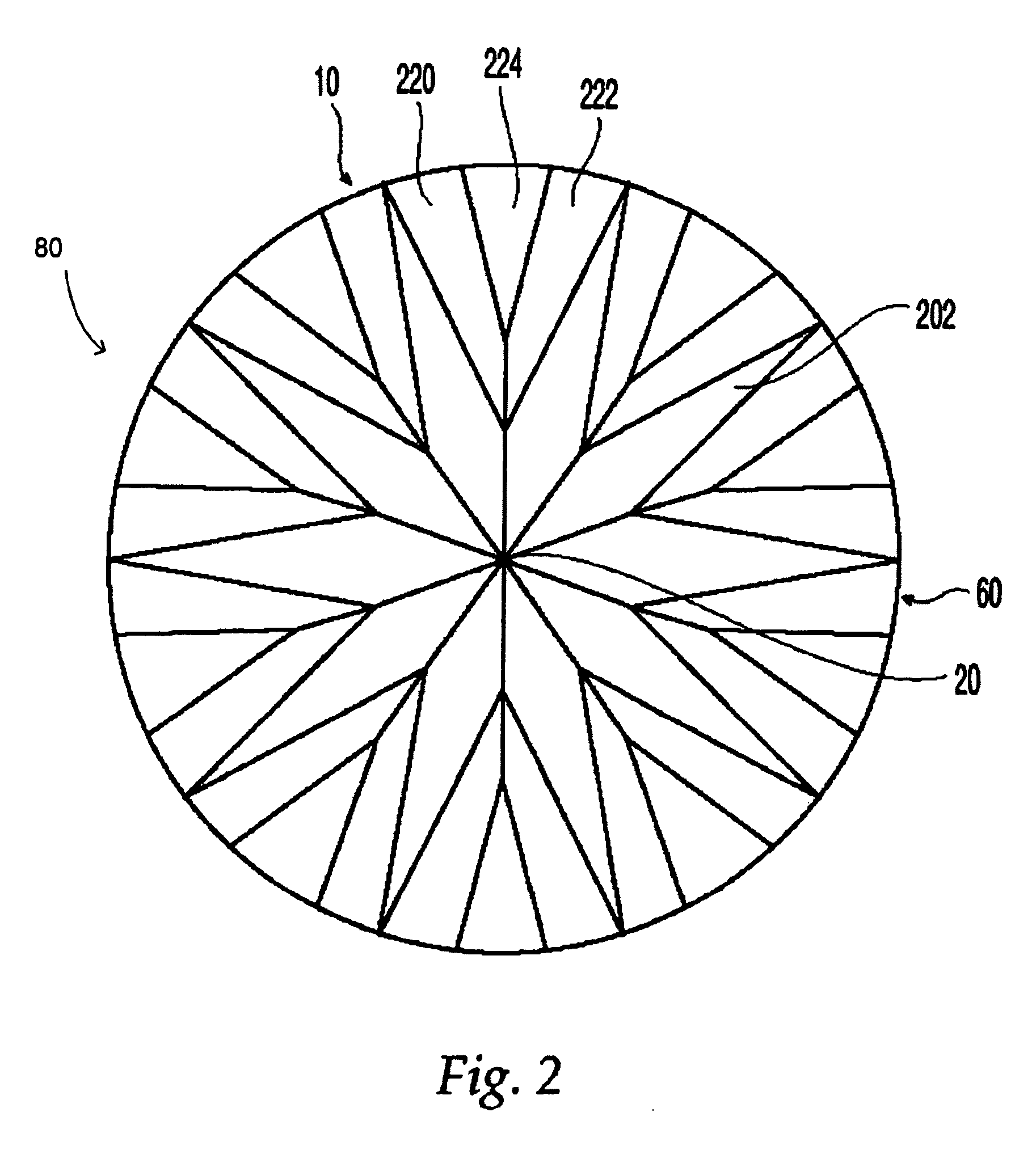
[0021] According to FIGS. 1-3, stone 10, such as a diamond, cut according to an embodiment of the present invention, is generally similar to a brilliant-cut diamond. Stone 10 has a generally round shape, when viewed from the top downward or bottom upward, and a generally pyramidal shape when viewed from the side. Stone 10 generally has girdle 60 defining the outer edge and widest portion of stone 10 in a top downward or bottom upward view; crown 40 defining the upper portion above girdle 60; pavilion 80 defining the lower portion below girdle 60; and culet 20 defining the lowest portion of pavilion 80. For purposes of explanation, features of stone 10 will be referenced with respect to central axis 12 that extends from culet 20 (FIG. 3), at a lower portion of stone 10, through the center of table 102, as represented by the dashed line 12 of FIG. 3. Furthermore, the outer edge of stone 10, girdle 60, will be referred to as the periphery of stone 10.

[0022]FIG. 1 shows a top view of a...


PUM


Abstract

A stone cut and method for cutting a stone that increase the number of facets on the stone as well as the scintillation, brilliance, and light reflectivity of the stone. The cut and method includes cutting angles and increased number of facets that, either separately or together, manage the external and internal light flow dynamics of a round cut diamond to a higher level of efficiency, effectiveness, and performance. In accordance with another aspect of the invention, different cutting angles and proportions generate greater brilliance, dispersion, scintillation, and light reflectivity of the stone.

Description

FIELD OF THE INVENTION [0001] Generally the present invention relates to a cut precious stone and a method for cutting a precious stone. More particularly the method for cutting and the cut of the present invention produces a precious stone with more brilliance, scintillation, and light dispersion. BACKGROUND OF THE INVENTION [0002] Traditionally, gemstones have been cut in many shapes and configurations over the ages. Typically, precious stones, such as diamonds, are cut to accent high coefficients of brilliancy, scintillation, and dispersion of light. In general, gemstones, particularly diamonds, should be cut such that light entering upper portions of the stone are is totally reflected and refracted within the stone, and also emerges back through the top portion of the stone to the eye of the observer. [0003] Many different stone cuts have attempted to bring out the greatest possible life of a diamond, i.e., give a diamond the most “fire” as possible. One such cut that has receiv...

Claims


Application Information

Patent Timeline
Patent Type & Authority Applications(United States)
IPC IPC(8): A44C17/00
CPCA44C17/001
Inventor SO, DAVID
Owner SO DAVID
Why Eureka
Try Eureka